## Diagram: Grid-Based Navigation Layout
### Overview
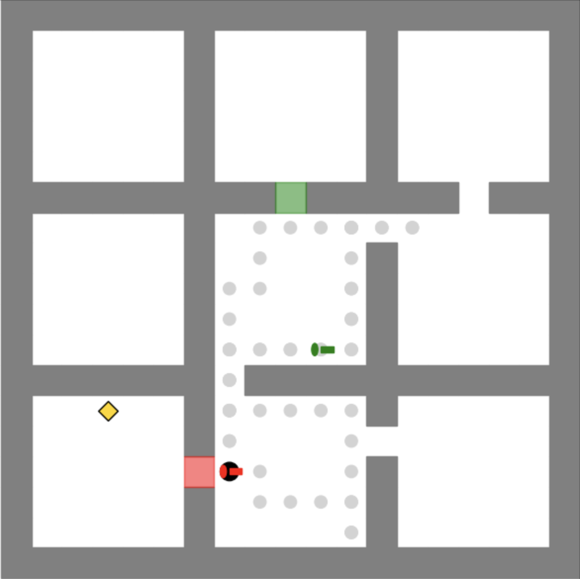
The image depicts a grid-based layout resembling a simplified floor plan or navigation map. It features a 3x3 grid of white rectangular "rooms" separated by gray pathways. Key elements include colored markers (yellow diamond, red square, green rectangle, black circle) and gray circular nodes along pathways. A legend on the right side correlates colors to symbolic meanings.
### Components/Axes
- **Grid Structure**:
- 3 rows and 3 columns of white rectangular rooms.
- Gray pathways form a cross-shaped network connecting rooms.
- **Legend** (right-aligned):
- **Yellow Diamond**: "Key"
- **Red Square**: "Start"
- **Green Rectangle**: "Exit"
- **Black Circle**: "Agent"
- **Gray Circles**: "Obstacles"
- **Gray Rectangle**: "Pathway"
- **Spatial Elements**:
- **Key**: Located in the bottom-left room (coordinates: bottom-left quadrant).
- **Start**: Positioned in the bottom-center room (coordinates: bottom-center quadrant).
- **Exit**: Situated in the top-center room (coordinates: top-center quadrant).
- **Agent**: Placed near the bottom-center room, adjacent to the Start marker.
- **Obstacles**: Gray circles distributed along pathways, primarily in the central and right-center regions.
- **Pathways**: Gray lines connecting rooms, with some nodes (gray circles) acting as waypoints or barriers.
### Detailed Analysis
- **Key Placement**: The yellow diamond ("Key") is isolated in the bottom-left room, suggesting it must be collected before reaching the Exit.
- **Agent Path**: The black circle ("Agent") starts near the red square ("Start") and faces a path toward the green rectangle ("Exit"), but must navigate around gray circular obstacles.
- **Pathway Nodes**: Gray circles along pathways may represent decision points, barriers, or waypoints. Their density increases toward the right-center, potentially indicating a more complex navigation zone.
- **Color Consistency**: All markers match their legend labels exactly (e.g., red square = Start, green rectangle = Exit).
### Key Observations
1. **Start-to-Exit Flow**: The Agent’s path from Start (red square) to Exit (green rectangle) requires traversing the central pathway while avoiding obstacles.
2. **Key Dependency**: The Key’s placement in the bottom-left room implies it may be a prerequisite for accessing the Exit or completing the task.
3. **Obstacle Distribution**: Gray circles are unevenly distributed, with higher concentration in the central and right-center pathways, creating potential bottlenecks.
4. **Agent Proximity**: The Agent is positioned close to the Start marker, suggesting an initial action or decision point.
### Interpretation
This diagram likely represents a pathfinding or decision-making scenario, such as:
- **Robotics Navigation**: The Agent (black circle) must navigate from Start to Exit while collecting the Key and avoiding obstacles.
- **Game Level Design**: The layout resembles a puzzle where the player must collect the Key before reaching the Exit, with obstacles adding complexity.
- **Logistical Planning**: The grid could model a warehouse or facility layout, with the Agent representing a worker or robot optimizing movement.
The absence of numerical data or explicit labels beyond the legend suggests the diagram prioritizes symbolic representation over quantitative analysis. The spatial arrangement emphasizes connectivity, dependency (Key → Exit), and environmental constraints (obstacles). The Agent’s proximity to the Start marker implies an immediate action, while the Key’s isolation highlights a critical resource management element.