\n
## Diagram: System Flow for Sending-End Physical System
### Overview
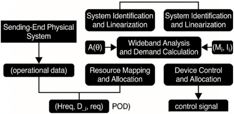
The image depicts a block diagram illustrating the flow of data and control signals within a system, likely related to communication or signal processing. The diagram shows a series of interconnected blocks representing different stages of processing, starting with a "Sending-End Physical System" and culminating in a "control signal".
### Components/Axes
The diagram consists of the following blocks:
* **Sending-End Physical System:** Top-left block.
* **System Identification and Linearization:** Two blocks positioned to the right of "Sending-End Physical System".
* **Wideband Analysis and Demand Calculation:** Central block, receiving input from "System Identification and Linearization" and "Sending-End Physical System".
* **Resource Mapping and Allocation:** Bottom-center block, receiving input from "Wideband Analysis and Demand Calculation".
* **Device Control and Allocation:** Bottom-right block, receiving input from "Resource Mapping and Allocation".
Additionally, the diagram includes the following labels representing data/signal flow:
* **(operational data)**: Flowing from "Sending-End Physical System" to "Wideband Analysis and Demand Calculation".
* **A(θ)**: Flowing from "System Identification and Linearization" to "Wideband Analysis and Demand Calculation".
* **(M₁, I₁)**: Flowing from "System Identification and Linearization" to "Wideband Analysis and Demand Calculation".
* **(Hreq, D₁, req)**: Flowing from "Wideband Analysis and Demand Calculation" to "Resource Mapping and Allocation".
* **POD**: Label associated with the flow from "Wideband Analysis and Demand Calculation" to "Resource Mapping and Allocation".
* **control signal**: Flowing from "Device Control and Allocation".
### Detailed Analysis or Content Details
The diagram illustrates a sequential process. The "Sending-End Physical System" generates "operational data" which is fed into the "Wideband Analysis and Demand Calculation" block. Simultaneously, the "System Identification and Linearization" block (appearing twice) provides inputs "A(θ)" and "(M₁, I₁)" to the "Wideband Analysis and Demand Calculation" block. The output of the "Wideband Analysis and Demand Calculation" block, labeled "(Hreq, D₁, req)" and "POD", is then passed to the "Resource Mapping and Allocation" block. Finally, the "Resource Mapping and Allocation" block sends a "control signal" to the "Device Control and Allocation" block.
### Key Observations
The diagram highlights a feedback-like structure, where system characteristics are identified and linearized to inform the analysis and demand calculation. The presence of two "System Identification and Linearization" blocks suggests either redundancy or parallel processing of different aspects of system identification. The labels within parentheses indicate specific data or parameters being transmitted between blocks.
### Interpretation
This diagram likely represents a control system for a physical system, possibly a transmitter or communication device. The "Sending-End Physical System" represents the actual hardware, while the subsequent blocks perform signal processing, resource allocation, and control functions. The "System Identification and Linearization" blocks are crucial for adapting the control strategy to the specific characteristics of the physical system. The "Wideband Analysis and Demand Calculation" block likely determines the required resources (bandwidth, power, etc.) based on the input signal and system conditions. The "Resource Mapping and Allocation" block then assigns these resources, and the "Device Control and Allocation" block implements the control actions. The diagram suggests a closed-loop control system where the system's performance is continuously monitored and adjusted to meet the desired specifications. The use of mathematical notations like A(θ), M₁, I₁, Hreq, D₁, and req indicates a quantitative approach to system analysis and control. The diagram does not provide specific numerical data or performance metrics, but it clearly outlines the functional relationships between different components of the system.