## Diagram: Entity-Relationship Data Model
### Overview
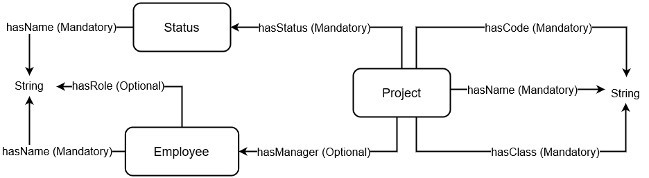
The image displays a technical diagram representing a data model or schema, illustrating three primary entities (Status, Employee, Project) and their relationships through directed attributes. The diagram uses rectangular boxes for entities and labeled arrows to denote properties and relationships, specifying whether each is mandatory or optional.
### Components/Axes
**Entities (Boxes):**
1. **Status** (Top-Left)
2. **Employee** (Bottom-Left)
3. **Project** (Center-Right)
**Attributes & Relationships (Labeled Arrows):**
* **From Status:**
* `hasName (Mandatory)` → points to `String` (data type).
* **From Employee:**
* `hasName (Mandatory)` → points to `String`.
* `hasRole (Optional)` → points to `String`.
* **From Project:**
* `hasCode (Mandatory)` → points to `String`.
* `hasName (Mandatory)` → points to `String`.
* `hasClass (Mandatory)` → points to `String`.
* `hasStatus (Mandatory)` → points to the `Status` entity.
* `hasManager (Optional)` → points to the `Employee` entity.
**Data Types:**
* `String` appears twice as the target data type for various attributes.
### Detailed Analysis
The diagram defines a structured schema with clear cardinality and optionality:
1. **Status Entity:**
* Has one mandatory attribute: `hasName`, which is a String.
2. **Employee Entity:**
* Has one mandatory attribute: `hasName` (String).
* Has one optional attribute: `hasRole` (String).
3. **Project Entity:**
* Has three mandatory attributes directly: `hasCode` (String), `hasName` (String), and `hasClass` (String).
* Has one mandatory relationship and one optional relationship to other entities:
* `hasStatus`: A Project must be associated with a Status entity.
* `hasManager`: A Project may optionally be associated with an Employee entity (acting as a manager).
**Spatial Grounding:**
* The `Status` entity is positioned in the upper-left quadrant.
* The `Employee` entity is positioned in the lower-left quadrant.
* The `Project` entity is positioned in the center-right area.
* The `String` data type nodes are placed at the far left and far right edges, serving as terminal points for attribute arrows.
* All relationship arrows flow from the source entity/attribute to the target entity/data type.
### Key Observations
* **Mandatory vs. Optional:** The schema explicitly distinguishes between mandatory and optional properties, which is critical for data validation and integrity.
* **Central Role of Project:** The `Project` entity is the most connected, serving as a hub that references both `Status` and `Employee`.
* **Asymmetric Relationships:** The relationship from `Project` to `Employee` (`hasManager`) is optional, while the relationship from `Project` to `Status` (`hasStatus`) is mandatory. This implies every project must have a status, but not necessarily a designated manager.
* **Data Type Consistency:** All leaf attributes (`hasName`, `hasRole`, `hasCode`, `hasClass`) are of type `String`.
### Interpretation
This diagram is a **conceptual or logical data model**, likely used in software engineering or database design. It defines the core business objects (Project, Employee, Status) and the rules governing their data.
* **What it demonstrates:** It specifies that a **Project** is a central object characterized by a unique code, a name, and a class. Crucially, every project must have a **Status** (e.g., "Active", "Completed", "On Hold") and may optionally have an **Employee** assigned as its manager. An **Employee** is defined by a name and an optional role.
* **Relationships:** The arrows define "has-a" relationships. The directionality is important: a Project *has a* Status, not the other way around. This establishes a clear dependency where the Project entity relies on the existence of a Status entity.
* **Underlying Logic:** The model enforces business rules at the schema level. For instance, a project cannot be created without linking it to a valid Status. The optionality of `hasManager` and `hasRole` provides flexibility, allowing for projects without managers and employees without formally defined roles.
* **Purpose:** This model would be used to design database tables (e.g., a `Project` table with foreign keys to `Status` and `Employee` tables) or to define classes in object-oriented programming. It serves as a blueprint for ensuring data consistency across a system.