\n
## Diagram: Multimodal Transformer Architecture
### Overview
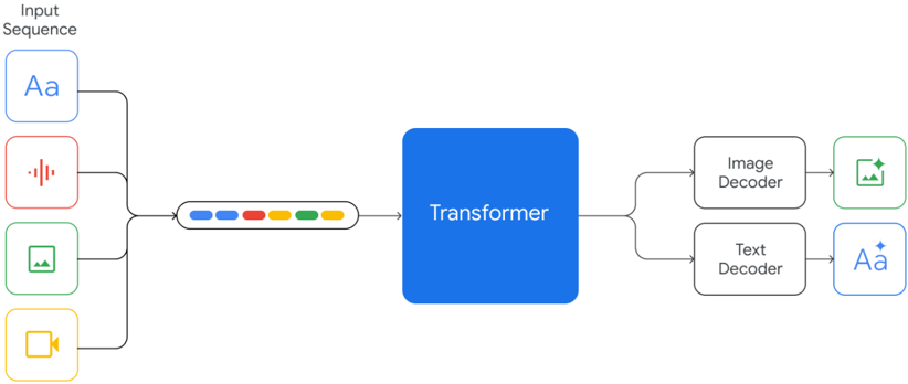
The image depicts a diagram illustrating the architecture of a multimodal transformer model. The model takes a sequence of different input modalities (text, audio, image, video) and processes them through a transformer network to generate corresponding outputs (image, text). The diagram emphasizes the flow of information from various input types into a central transformer block, and then branching out to modality-specific decoders.
### Components/Axes
The diagram consists of the following components:
* **Input Sequence:** Located on the left side of the diagram, this section represents the various input modalities.
* **Text Input:** Represented by a light blue rounded rectangle with the letter "Aa" inside.
* **Audio Input:** Represented by a red rounded rectangle with a sound wave icon inside.
* **Image Input:** Represented by a green rounded rectangle with a grid icon inside.
* **Video Input:** Represented by a yellow rounded rectangle with a play button icon inside.
* **Transformer:** A large blue rectangle in the center of the diagram, labeled "Transformer".
* **Image Decoder:** A light green rounded rectangle labeled "Image Decoder".
* **Text Decoder:** A light blue rounded rectangle labeled "Text Decoder".
* **Arrows:** Yellow arrows indicate the flow of information from the input modalities to the transformer, and from the transformer to the decoders. A series of colored dots (blue, orange, green) connect the input sequence to the transformer.
### Detailed Analysis or Content Details
The diagram shows a sequential input process. The input sequence consists of four modalities: text, audio, image, and video. These inputs are fed into a transformer network. The transformer then outputs to two decoders: an image decoder and a text decoder.
The input modalities are represented by distinct icons within rounded rectangles:
* Text: "Aa"
* Audio: Sound wave icon
* Image: Grid icon
* Video: Play button icon
The arrows connecting the inputs to the transformer are yellow, indicating the flow of information. The colored dots (blue, orange, green) between the input sequence and the transformer likely represent different stages or layers within the transformer's processing of the input sequence.
The outputs of the transformer are directed to two decoders:
* Image Decoder: Outputs an image (represented by a grid icon).
* Text Decoder: Outputs text (represented by "Aa").
### Key Observations
The diagram highlights the versatility of the transformer architecture in handling multiple input modalities. The central role of the transformer suggests it acts as a unifying processing unit for all input types. The separate decoders indicate that the transformer can generate outputs in different modalities based on the input.
### Interpretation
This diagram illustrates a multimodal transformer model, a type of neural network capable of processing and generating data across different modalities (text, audio, image, video). The transformer architecture is known for its ability to capture long-range dependencies in sequential data, making it well-suited for handling complex multimodal inputs. The diagram suggests that the model learns a shared representation of the input modalities within the transformer, allowing it to generate outputs in different modalities. This type of model has applications in areas such as image captioning, video description, and multimodal search. The use of separate decoders for image and text suggests that the model is designed to generate outputs tailored to each modality.