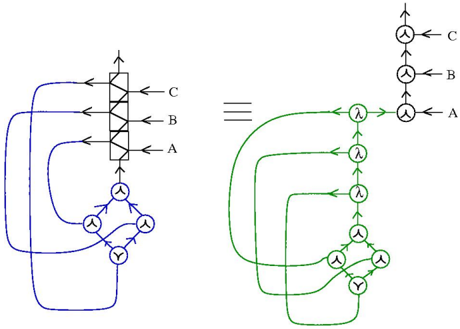
## Diagram: Equivalent Representations of a System
### Overview
The image presents two equivalent diagrams representing a system. The diagram on the left is rendered in blue, while the equivalent diagram on the right is rendered in green. The two diagrams are separated by an equals sign made of three horizontal lines. Both diagrams have inputs labeled A, B, and C.
### Components/Axes
**Left Diagram (Blue):**
* **Inputs:** Labeled A, B, and C, exiting from the right side of a vertical rectangular block.
* **Vertical Block:** A rectangular block with three diagonal lines inside, each corresponding to an input (A, B, C). An arrow points upwards into the bottom of the block.
* **Bottom Component:** A diamond shape composed of four nodes connected by arrows. Each node contains a circle with a "Y" shape inside, except for the bottom node, which contains a "Y" shape without the circle. Arrows indicate the flow direction between the nodes.
* **Connections:** Curved lines connect the outputs A, B, and C to the nodes in the diamond shape.
**Right Diagram (Green):**
* **Inputs:** Labeled A, B, and C, exiting from the right side of a vertical chain of nodes.
* **Vertical Chain:** A series of nodes connected by arrows pointing upwards. The top two nodes are circles with a "Y" shape inside. Below them are three nodes containing a circle with a "λ" (lambda) symbol inside.
* **Bottom Component:** A diamond shape composed of four nodes connected by arrows. Each node contains a circle with a "Y" shape inside, except for the bottom node, which contains a "Y" shape without the circle. Arrows indicate the flow direction between the nodes.
* **Connections:** Curved lines connect the nodes containing "λ" to the nodes in the diamond shape.
### Detailed Analysis or ### Content Details
**Left Diagram (Blue):**
* Input A connects to the bottom-right node of the diamond.
* Input B connects to the top-right node of the diamond.
* Input C connects to the top-left node of the diamond.
**Right Diagram (Green):**
* The bottom node containing "λ" connects to the bottom-right node of the diamond.
* The middle node containing "λ" connects to the top-right node of the diamond.
* The top node containing "λ" connects to the top-left node of the diamond.
### Key Observations
* The two diagrams are visually distinct but represent the same underlying system.
* The vertical block in the left diagram is equivalent to the vertical chain of nodes with "λ" in the right diagram.
* The diamond-shaped component is identical in both diagrams.
* The connections between the inputs and the diamond component are re-routed through the vertical chain in the right diagram.
### Interpretation
The image illustrates two different ways to represent the same system or process. The left diagram uses a more compact representation with a vertical block, while the right diagram uses a more detailed representation with a chain of nodes containing "λ". The "λ" symbol likely represents a specific operation or transformation applied to the signals. The equivalence of the two diagrams suggests that the vertical block in the left diagram performs the same function as the chain of "λ" nodes in the right diagram. The diamond-shaped component likely represents a common processing element used in both representations. The diagram demonstrates how a complex system can be represented in multiple ways, each with its own advantages and disadvantages in terms of clarity and detail.