## Diagram: Out-of-Order Execution Pipeline
### Overview
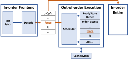
The image is a block diagram illustrating the pipeline of an out-of-order execution processor. It shows the flow of instructions from the in-order frontend, through the out-of-order execution core, and finally to the in-order retire stage. The diagram highlights the presence of "fence" instructions and their impact on the pipeline.
### Components/Axes
The diagram consists of the following key components:
1. **In-order Frontend:**
* **Inst Fetch:** Instruction Fetch unit.
* **Decode:** Instruction Decode unit.
2. **μOp's:** Micro-operations buffer. Contains entries for:
* `fence` (highlighted in orange)
* `Id` (Load instruction)
* `...` (Indicates more entries)
3. **Out-of-order Execution:**
* **Scheduler:** Schedules micro-operations for execution.
* **Load/Store Buffer:**
* `older_access`
* `fence` (highlighted in orange)
* `Id` (Load instruction)
* `...` (Indicates more entries)
* **ALU...:** Arithmetic Logic Unit (and other execution units).
* **Cache/Mem:** Cache and Memory system.
4. **In-order Retire:** In-order retirement stage.
### Detailed Analysis
* **Flow of Instructions:** Instructions flow from left to right, starting with the In-order Frontend, then to the μOp's buffer, then to the Out-of-order Execution core, and finally to the In-order Retire stage.
* **In-order Frontend:** The In-order Frontend consists of the Instruction Fetch and Decode units. Instructions are fetched and decoded in order.
* **μOp's Buffer:** The decoded instructions are stored as micro-operations (μOp's) in a buffer. The diagram explicitly shows "fence" and "Id" (Load) instructions. The "fence" instruction is highlighted in orange.
* **Out-of-order Execution:** The Scheduler selects and dispatches micro-operations for execution based on data dependencies and resource availability. The Load/Store Buffer manages memory operations. The ALU performs arithmetic and logical operations. The Cache/Mem system provides access to memory. The Load/Store Buffer also contains "fence" and "Id" instructions, with "fence" highlighted in orange.
* **In-order Retire:** The In-order Retire stage ensures that instructions are retired in the order they were fetched, maintaining program order.
* **Fence Instructions:** The "fence" instructions are highlighted in orange and appear in the μOp's buffer and the Load/Store Buffer. An orange arrow bypasses the Out-of-order Execution block, going directly to the In-order Retire block. This suggests that "fence" instructions enforce ordering constraints and may bypass the out-of-order execution core.
### Key Observations
* The diagram emphasizes the out-of-order execution core, which allows instructions to be executed in a different order than they were fetched, improving performance.
* The "fence" instructions are treated specially, potentially bypassing the out-of-order execution core to enforce memory ordering.
### Interpretation
The diagram illustrates a typical out-of-order execution pipeline with a focus on how "fence" instructions are handled. "Fence" instructions are synchronization primitives that enforce memory ordering constraints. The diagram suggests that "fence" instructions may bypass the out-of-order execution core to ensure that memory operations are performed in the correct order. This is crucial for maintaining program correctness in multi-threaded environments. The orange highlighting and bypass arrow emphasize the special handling of "fence" instructions in the pipeline. The presence of "fence" instructions in both the μOp's buffer and the Load/Store Buffer indicates that they affect both instruction scheduling and memory access ordering.