\n
## Diagram: Processor Pipeline Architecture
### Overview
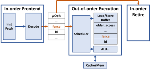
The image depicts a simplified block diagram of a processor pipeline, illustrating the stages of instruction processing from fetch to retire. It highlights the transition from in-order frontend to out-of-order execution and finally to in-order retire. The diagram emphasizes the flow of instructions and the key components involved in each stage.
### Components/Axes
The diagram consists of three main blocks:
1. **In-order Frontend:** Contains "Inst Fetch" (Instruction Fetch) and "Decode" stages.
2. **Out-of-order Execution:** Contains "μOps" (Micro-operations), "Scheduler", "Load/Store Buffer", and "ALU...".
3. **In-order Retire:** The final stage of the pipeline.
Additionally, there's a "Cache/Mem" block at the bottom, representing the memory interface.
Key labels within the blocks include:
* "fence" (appears twice, once in μOps and once in Load/Store Buffer)
* "Id" (appears twice, once in μOps and once in Load/Store Buffer)
* "older_access" (within Load/Store Buffer)
* "ALU..." (within Out-of-order Execution)
Arrows indicate the flow of instructions between stages. An orange arrow connects the "Decode" stage to the "μOps" stage, and another orange arrow connects the "Out-of-order Execution" to the "In-order Retire" stage. A blue arrow connects the "Out-of-order Execution" to the "Cache/Mem".
### Detailed Analysis / Content Details
The diagram illustrates a processor pipeline with the following stages:
1. **Instruction Fetch:** Instructions are fetched from memory.
2. **Decode:** Instructions are decoded into micro-operations (μOps).
3. **Out-of-order Execution:**
* μOps are generated and placed in a queue. The "fence" and "Id" labels suggest control or identification mechanisms within this queue.
* The "Scheduler" reorders μOps for efficient execution.
* The "Load/Store Buffer" handles memory access operations, with "older_access" indicating a mechanism for managing memory access order. The "fence" and "Id" labels are also present here.
* The "ALU..." block represents the arithmetic logic unit, where computations are performed.
4. **In-order Retire:** Instructions are committed in their original program order.
The "Cache/Mem" block represents the interaction with the cache and main memory. The blue arrow indicates that the out-of-order execution stage interacts with the cache/memory.
The "fence" label appears in both the μOps and Load/Store Buffer sections, suggesting a synchronization point or barrier within the pipeline. The "Id" label also appears in both sections, potentially representing an instruction identifier.
### Key Observations
* The pipeline is divided into in-order frontend and in-order retire stages, with an out-of-order execution core in between.
* The "fence" and "Id" labels are repeated in different parts of the pipeline, suggesting their importance in managing instruction flow and synchronization.
* The Load/Store Buffer is a critical component for handling memory access operations.
* The diagram is a high-level representation and does not include details about specific pipeline stages or optimizations.
### Interpretation
This diagram illustrates a common processor architecture that leverages out-of-order execution to improve performance. The in-order frontend ensures correct instruction sequencing, while the out-of-order execution core allows for parallel execution of independent instructions. The in-order retire stage guarantees that instructions are committed in the correct order, maintaining program correctness.
The presence of "fence" and "Id" labels suggests mechanisms for managing dependencies and ensuring proper synchronization within the pipeline. The Load/Store Buffer is essential for handling memory access operations efficiently.
The diagram highlights the trade-offs between in-order and out-of-order execution. In-order execution is simpler to implement but can limit performance due to dependencies between instructions. Out-of-order execution can improve performance but requires more complex control logic to ensure correctness. The architecture shown in the diagram attempts to balance these trade-offs by using in-order frontend and retire stages with an out-of-order execution core.