## Diagram Type: Flowchart
### Overview
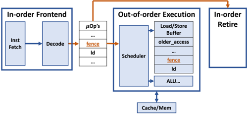
The image is a flowchart that illustrates the process of executing instructions in a computer system. It shows the sequence of operations from fetching instructions to retiring them, with a focus on out-of-order execution.
### Components/Axes
- **In-order Frontend**: This section includes the fetch and decode stages, where instructions are retrieved from memory and processed.
- **Out-of-order Execution**: This section shows the execution of instructions in a non-linear order, with the scheduler managing the execution of instructions that are ready.
- **In-order Retire**: This section shows the retirement of instructions that have been executed in the correct order.
- **μOp's**: This section represents micro-operations, which are the basic units of execution in the processor.
- **Load/Store Buffer**: This section represents the buffer used to hold instructions that are being executed.
- **Scheduler**: This section represents the scheduler that manages the execution of instructions.
- **ALU**: This section represents the Arithmetic Logic Unit, which performs arithmetic and logical operations.
- **Cache/Mem**: This section represents the cache and memory, which store data and instructions.
### Detailed Analysis or ### Content Details
- The flowchart shows that instructions are fetched from memory and decoded.
- The scheduler manages the execution of instructions that are ready, even if they are not in the correct order.
- The load/store buffer holds instructions that are being executed.
- The ALU performs arithmetic and logical operations.
- The cache and memory store data and instructions.
### Key Observations
- The flowchart shows that instructions can be executed in a non-linear order, which can improve performance.
- The scheduler is responsible for managing the execution of instructions that are ready.
- The load/store buffer is used to hold instructions that are being executed.
- The ALU performs arithmetic and logical operations.
- The cache and memory store data and instructions.
### Interpretation
The flowchart illustrates the process of executing instructions in a computer system, with a focus on out-of-order execution. The scheduler is responsible for managing the execution of instructions that are ready, even if they are not in the correct order. The load/store buffer is used to hold instructions that are being executed, and the ALU performs arithmetic and logical operations. The cache and memory store data and instructions. The flowchart shows that instructions can be executed in a non-linear order, which can improve performance.