## Diagram: Braking System Logic
### Overview
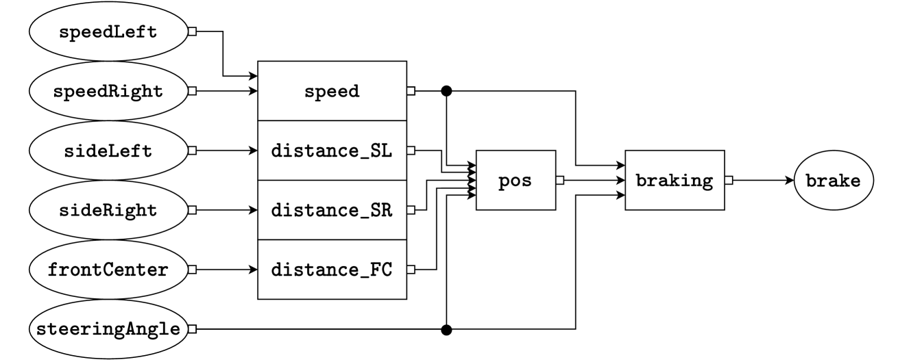
The image is a block diagram illustrating the logic flow of a braking system. It shows how various sensor inputs (speed, distance, steering angle) are processed to determine the braking force.
### Components/Axes
* **Input Sensors (Left Side):** These are represented by ovals.
* `speedLeft`: Left wheel speed.
* `speedRight`: Right wheel speed.
* `sideLeft`: Distance to an object on the left side.
* `sideRight`: Distance to an object on the right side.
* `frontCenter`: Distance to an object in front.
* `steeringAngle`: Steering wheel angle.
* **Processing Blocks (Center):** These are represented by rectangles.
* `speed`: Processes `speedLeft` and `speedRight`.
* `distance_SL`: Processes `sideLeft`.
* `distance_SR`: Processes `sideRight`.
* `distance_FC`: Processes `frontCenter`.
* `pos`: Processes the outputs of `speed`, `distance_SL`, `distance_SR`, and `distance_FC`.
* `braking`: Processes the output of `pos`.
* **Output (Right Side):**
* `brake`: Represented by an oval, indicating the final braking output.
* **Connections:** Lines with arrowheads indicate the flow of information between the components.
### Detailed Analysis
* `speedLeft` and `speedRight` feed into the `speed` processing block.
* `sideLeft` feeds into the `distance_SL` processing block.
* `sideRight` feeds into the `distance_SR` processing block.
* `frontCenter` feeds into the `distance_FC` processing block.
* The outputs of `speed`, `distance_SL`, `distance_SR`, and `distance_FC` are inputs to the `pos` processing block.
* The output of `pos` is the input to the `braking` processing block.
* The output of `braking` is the final `brake` output.
* There is a feedback loop from the output of the `speed` block to the input of the `pos` block.
* There is a feedback loop from the output of the `distance_FC` block to the input of the `pos` block.
### Key Observations
* The diagram illustrates a closed-loop control system for braking.
* Multiple sensor inputs are used to determine the braking force.
* The `pos` block appears to be a central processing unit that integrates the sensor data.
* The `braking` block likely implements the braking control algorithm.
### Interpretation
The diagram represents a simplified model of an advanced braking system, potentially an anti-lock braking system (ABS) or an autonomous emergency braking (AEB) system. The system uses various sensors to monitor the vehicle's speed, proximity to obstacles, and steering angle. This information is then processed to determine the appropriate braking force, which is applied to the wheels. The feedback loops suggest that the system continuously adjusts the braking force based on the vehicle's response. The system aims to optimize braking performance and prevent skidding or collisions.