## State Transition Diagram: Protein-Protein Interaction Network
### Overview
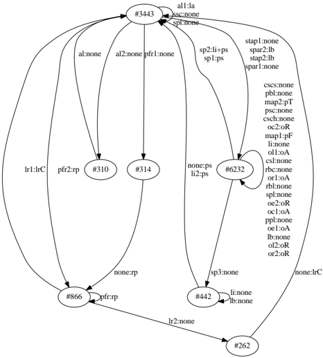
The image is a state transition diagram representing a protein-protein interaction network. Nodes represent proteins (identified by numerical IDs), and directed edges represent interactions between them. Each edge is labeled with the type of interaction or modification occurring between the connected proteins.
### Components/Axes
* **Nodes:** Represented as circles, each containing a numerical identifier (e.g., #3443, #310, #314, #6232, #866, #442, #262).
* **Edges:** Represented as directed arrows, indicating the direction of interaction. Each edge is labeled with interaction types (e.g., "all:la", "lr1:lrC", "pfr:rp").
* **Labels:** Textual annotations associated with nodes and edges, describing protein IDs and interaction types.
### Detailed Analysis
Here's a breakdown of the connections and labels:
* **Node #3443 (Top Center):**
* Has a self-loop labeled "all:la", "ssc:none", "spl:none".
* Has outgoing edges to:
* #310, labeled "al:none".
* #314, labeled "al2:none", "pfr1:none".
* #6232, labeled "sp2:li+ps", "sp1:ps".
* #866, labeled "lr1:lrC".
* #442, labeled "none:ps", "li2:ps".
* **Node #6232 (Right Center):**
* Has a self-loop labeled "stap1:none", "spar2:lb", "stap2:lb", "spar1:none".
* Also labeled with: "cscs:none", "pbl:none", "map2:pT", "psc:none", "csch:none", "oc2:oR", "map1:pF", "li:none", "oll:oA", "csl:none", "rbc:none", "orl:oA", "rbl:none", "spl:none", "oe2:oR", "oc1:oA", "ppl:none", "oe1:oA", "lb:none", "ol2:oR", "or2:oR".
* Has an outgoing edge to #866, labeled "pfr2:rp".
* **Node #310 (Left Center):**
* Has an outgoing edge to #866, labeled "none:rp".
* **Node #314 (Center):**
* Has an outgoing edge to #866, labeled "pfr:rp".
* **Node #442 (Bottom Center):**
* Has a self-loop labeled "li:none", "lb:none".
* Has an outgoing edge to #262, labeled "lr2:none".
* **Node #866 (Bottom Left):**
* Has an outgoing edge to #3443, labeled "none:lrC".
* **Node #262 (Bottom Right):**
* No outgoing edges are visible.
### Key Observations
* Node #3443 appears to be a central node, with connections to most other nodes in the network.
* Node #6232 has a large number of labels associated with it, suggesting it may represent a complex protein or a hub in the network.
* The labels on the edges indicate different types of interactions or modifications between the proteins.
### Interpretation
This diagram represents a protein-protein interaction network, where nodes are proteins and edges are interactions. The labels on the edges provide information about the type of interaction. The network structure suggests that protein #3443 may play a regulatory role, as it interacts with many other proteins. Protein #6232 also appears to be important, given the number of labels associated with it. The diagram could be used to understand the flow of information or signals through the network, and to identify potential targets for therapeutic intervention. The "none" labels may indicate a lack of a specific interaction or modification. The labels ending in "la", "lb", "lrc", "rp", "ps", "pT", "pF", "oA", "oR" may indicate specific types of modifications or interactions.