## Directed Graph Diagram: State Transition Network
### Overview
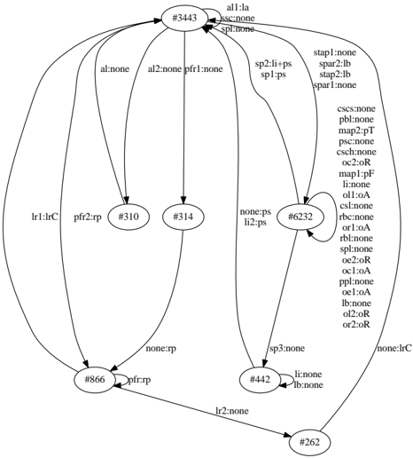
The image displays a directed graph (state transition diagram) consisting of seven circular nodes connected by directed edges (arrows). Each node contains a unique identifier prefixed with a hash symbol (e.g., #3443). The edges are labeled with text strings, typically in a `key:value` format, indicating the condition or action associated with the transition. The diagram appears to model a system's states and the transitions between them, likely from a technical or computational context.
### Components/Axes
* **Nodes (States):** There are 7 nodes, each represented by a circle with a unique ID.
* #3443 (Top-center)
* #310 (Left of center)
* #314 (Center)
* #6232 (Right of center)
* #866 (Bottom-left)
* #442 (Bottom-center)
* #262 (Bottom-right)
* **Edges (Transitions):** Directed arrows connect the nodes. Each arrow has a text label describing the transition.
* **Legend/Axis Titles:** Not applicable. This is a graph diagram, not a chart with axes or a formal legend. The labels on the edges serve as the primary descriptive information.
### Detailed Analysis
**Node and Edge Inventory:**
1. **Node #3443 (Top-center):** This node has the highest number of outgoing transitions (8).
* **Outgoing Edges:**
* To #310: Label `al:none`
* To #314: Label `al2:none pfr1:none`
* To #866: Label `lr1:lrC`
* To #6232: Label `sp2:li+ps sp1:ps`
* To #442: Label `sp3:none`
* To #262: Label `none:lrC`
* Self-loop: Label `all:la asc:none spl:none`
* **Incoming Edges:** From #6232 (label `none:ps li2:ps`).
2. **Node #310 (Left of center):**
* **Outgoing Edge:** To #866. Label `pfr2:rp`.
* **Incoming Edge:** From #3443 (label `al:none`).
3. **Node #314 (Center):**
* **Outgoing Edge:** To #866. Label `none:rp`.
* **Incoming Edge:** From #3443 (label `al2:none pfr1:none`).
4. **Node #6232 (Right of center):** This node has a complex set of labels on its self-loop and one outgoing edge.
* **Outgoing Edge:** To #3443. Label `none:ps li2:ps`.
* **Self-loop:** A large block of text is associated with this loop. The text is arranged vertically to the right of the node.
* `stap1:none`
* `spar2:lb`
* `stap2:lb`
* `spar1:none`
* `csc:none`
* `pbl:none`
* `map2:pF`
* `pbc:none`
* `csch:none`
* `oc2:oF`
* `map1:pF`
* `oll:oA`
* `cs1:none`
* `rbc:none`
* `oc1:oA`
* `pbl:none`
* `oe2:oR`
* `oc2:oA`
* `ppl:none`
* `oe1:oA`
* `lb:none`
* `al2:oR`
* `al1:oA`
* **Incoming Edge:** From #3443 (label `sp2:li+ps sp1:ps`).
5. **Node #866 (Bottom-left):**
* **Outgoing Edge:** To #442. Label `lr2:none`.
* **Incoming Edges:**
* From #3443 (label `lr1:lrC`).
* From #310 (label `pfr2:rp`).
* From #314 (label `none:rp`).
6. **Node #442 (Bottom-center):**
* **Outgoing Edge:** To #262. Label `li:none lb:none`.
* **Incoming Edges:**
* From #3443 (label `sp3:none`).
* From #866 (label `lr2:none`).
7. **Node #262 (Bottom-right):**
* **Outgoing Edge:** None visible.
* **Incoming Edges:**
* From #3443 (label `none:lrC`).
* From #442 (label `li:none lb:none`).
### Key Observations
* **Central Hub:** Node #3443 acts as a central hub, with transitions to every other node in the graph except #262 (it connects to #262 directly, but not via an intermediate node). It also has a self-loop.
* **Terminal Node:** Node #262 appears to be a terminal or sink state, as it has no outgoing transitions.
* **Complex State:** Node #6232 has a highly detailed self-loop with 22 distinct labeled parameters, suggesting it represents a complex state with many internal conditions or sub-processes.
* **Transition Labels:** The labels follow a consistent pattern of `identifier:value` (e.g., `al:none`, `pfr2:rp`). The identifiers (like `al`, `pfr`, `sp`, `lr`, `oc`, `map`) likely represent specific system signals, flags, or conditions. The values (`none`, `rp`, `lb`, `oA`, `pF`) are the states or results of those conditions.
* **Flow Direction:** The overall flow is generally downward and to the right, from #3443 towards #262, with #866 and #442 acting as intermediate nodes.
### Interpretation
This diagram is a formal model of a finite state machine or a similar state-based system. The nodes represent discrete states the system can be in, and the labeled edges represent the transitions between those states, triggered by specific conditions or events encoded in the labels.
* **System Logic:** The graph defines the complete operational logic of the system. For example, from state #3443, if condition `al` is `none`, the system moves to state #310. If condition `sp2` is `li+ps` and `sp1` is `ps`, it moves to state #6232.
* **Complexity and Hierarchy:** The disparity in complexity between nodes (e.g., the simple #310 vs. the highly parameterized #6232) suggests a hierarchical or modular system design. State #6232 likely handles a major subsystem with many internal variables.
* **Potential Purpose:** Given the technical nature of the labels (e.g., `map1:pF`, `oc2:oF`), this could model a network protocol, a hardware control unit, a compiler's state machine, or a business process workflow. The exact meaning of the identifiers (`pfr`, `sp`, `lr`, `oc`) would be defined in the accompanying technical specification.
* **Investigative Reading:** The graph allows one to trace all possible execution paths. For instance, a path from the start (#3443) to the end (#262) could be: `#3443 -> (sp3:none) -> #442 -> (li:none lb:none) -> #262`. The presence of multiple paths to #262 (direct from #3443 or via #442) indicates alternative routes or conditions for reaching that terminal state. The self-loops on #3443 and #6232 indicate states where the system can remain while processing internal events without changing its high-level state.