## NetworkDiagram: Conditional Workflow with Node Connections
### Overview
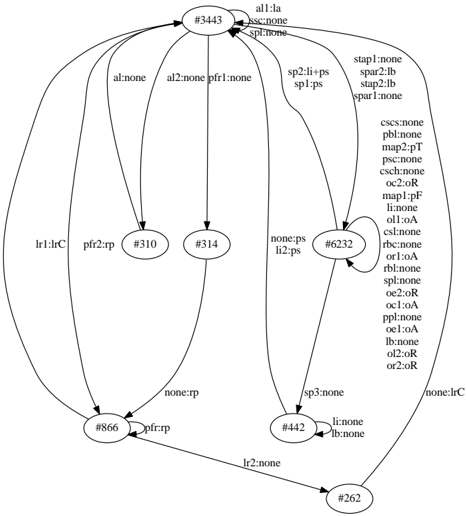
The image depicts a complex network diagram with interconnected nodes and directional arrows. Nodes are labeled with identifiers (e.g., `#344`, `#310`) and descriptive text (e.g., `all:la`, `al:l-none`). Arrows between nodes carry labels indicating conditions or actions (e.g., `pf1:r-none`, `sp1:ps`). A legend on the right maps colors to specific labels, suggesting categorical relationships.
### Components/Axes
- **Nodes**:
- Labeled with identifiers (e.g., `#344`, `#310`, `#314`, `#866`, `#6232`, `#442`, `#262`).
- Each node contains descriptive text (e.g., `all:la`, `al:l-none`, `pf1:r-none`).
- **Arrows**:
- Directional connections between nodes.
- Labels on arrows include conditions/actions (e.g., `pf1:r-none`, `sp1:ps`, `lr1:lrC`).
- **Legend**:
- Located on the right side.
- Maps colors to labels (e.g., `all:la` = dark blue, `al:l-none` = light blue, `pf1:r-none` = gray).
### Detailed Analysis
- **Node Connections**:
- Node `#344` (top-center) connects to `#310`, `#314`, `#866`, and `#6232` via arrows labeled `all:la`, `al:l-none`, `pf1:r-none`, and `none:ps`, respectively.
- Node `#310` connects to `#314` via `pf2:r-p`.
- Node `#314` connects to `#866` via `none:rp`.
- Node `#866` connects to `#442` via `pf1:r-p`.
- Node `#6232` connects to `#442` via `sp3:none`.
- Node `#442` connects to `#262` via `lr2:none`.
- **Legend**:
- Colors correspond to labels (e.g., `all:la` = dark blue, `al:l-none` = light blue, `pf1:r-none` = gray).
- Some labels (e.g., `csc:c-none`, `pb1:l-none`) appear in the legend but lack direct connections in the diagram.
### Key Observations
1. **Central Node**: `#344` acts as a hub, distributing to multiple downstream nodes.
2. **Conditional Flow**: Arrows with labels like `pf1:r-none` and `sp1:ps` suggest decision points or conditional transitions.
3. **Termination Nodes**: `#262` and `#866` have fewer outgoing connections, potentially indicating endpoints.
4. **Unused Labels**: Some legend entries (e.g., `csc:c-none`, `pb1:l-none`) are not visually represented in the diagram.
### Interpretation
The diagram likely represents a conditional workflow or decision tree, where nodes symbolize states or steps, and arrows denote transitions based on specific conditions (e.g., `pf1:r-none`). The central node `#344` may represent an initial state, branching into sub-processes (e.g., `#310`, `#314`). The presence of `none` in labels (e.g., `none:ps`) suggests default or fallback paths. The legend’s color coding reinforces categorical distinctions, though some labels lack visual representation, hinting at potential gaps or unused conditions.
**Note**: The diagram lacks numerical data or trends, focusing instead on structural relationships and conditional logic.