## Communication System Diagram
### Overview
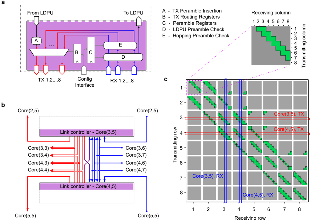
The image presents a communication system diagram, comprising three sub-figures (a, b, and c). Sub-figure (a) illustrates a high-level block diagram of a communication module, showing data flow and key components. Sub-figure (b) depicts a link controller setup with multiple cores and their interconnections. Sub-figure (c) displays a matrix representing the communication paths between transmitting and receiving columns/rows.
### Components/Axes
**Sub-figure a:**
* **Labels:**
* "From LDPU" (top-left)
* "To LDPU" (top-right)
* "TX 1,2,...8" (bottom-left)
* "Config Interface" (bottom-center)
* "RX 1,2,...8" (bottom-right)
* "A - TX Peramble Insertion" (top-right, outside the diagram)
* "B - TX Routing Registers" (top-right, outside the diagram)
* "C - Peramble Registers" (top-right, outside the diagram)
* "D - LDPU Preamble Check" (top-right, outside the diagram)
* "E - Hopping Preamble Check" (top-right, outside the diagram)
* **Components:**
* Block A (TX Peramble Insertion)
* Block B (TX Routing Registers)
* Block C (Peramble Registers)
* Block D (LDPU Preamble Check)
* Block E (Hopping Preamble Check)
* **Data Flow:**
* Red arrows indicate transmission (TX) paths.
* Blue arrows indicate reception (RX) paths.
**Sub-figure b:**
* **Labels:**
* "Core(2,5)" (top-left and top-right)
* "Core(3,3)", "Core(3,4)", "Core(4,3)", "Core(4,4)" (left side)
* "Core(3,6)", "Core(3,7)", "Core(4,6)", "Core(4,7)" (right side)
* "Core(5,5)" (bottom-left and bottom-right)
* "Link controller - Core(3,5)" (top center)
* "Link controller - Core(4,5)" (bottom center)
* **Data Flow:**
* Red arrows indicate transmission (TX) paths.
* Blue arrows indicate reception (RX) paths.
**Sub-figure c:**
* **Axes:**
* X-axis: "Receiving row" (labeled 1 to 8)
* Y-axis: "Transmitting row" (labeled 1 to 8)
* **Elements:**
* Green blocks indicate active communication paths.
* Gray blocks indicate inactive communication paths.
* **Annotations:**
* "Core(3,5), TX" (right of row 3)
* "Core(4,5), TX" (right of row 4)
* "Core(3,5), RX" (left of row 7)
* "Core(4,5), RX" (left of row 8)
* **Inset:**
* "Receiving column" (labeled 1 to 8)
* "Transmitting column" (labeled 1 to 8)
* Shows a zoomed-in view of the communication paths.
### Detailed Analysis or ### Content Details
**Sub-figure a:**
* The diagram shows a module that handles both transmission (TX) and reception (RX) of data.
* The "Config Interface" likely allows for configuration of the module's parameters.
* The blocks A, B, C, D, and E represent different stages in the TX and RX processes, including preamble insertion, routing, and checks.
**Sub-figure b:**
* Two link controllers, "Core(3,5)" and "Core(4,5)", are shown.
* Each link controller is connected to multiple cores.
* The red arrows indicate data transmission from "Core(3,3)", "Core(3,4)", "Core(4,3)", "Core(4,4)" to "Core(3,5)" and "Core(4,5)".
* The blue arrows indicate data reception from "Core(3,5)" and "Core(4,5)" to "Core(3,6)", "Core(3,7)", "Core(4,6)", "Core(4,7)".
**Sub-figure c:**
* The matrix represents the communication paths between transmitting and receiving rows.
* Green blocks indicate active communication paths, forming diagonal patterns.
* The inset provides a zoomed-in view of the communication paths.
* The annotations "Core(3,5), TX", "Core(4,5), TX", "Core(3,5), RX", and "Core(4,5), RX" indicate the transmitting and receiving cores for specific rows.
* The green blocks are present in a diagonal pattern, offset by one position each row.
### Key Observations
* Sub-figure (a) provides a high-level overview of the communication module.
* Sub-figure (b) illustrates the interconnection between link controllers and cores.
* Sub-figure (c) visualizes the communication paths between transmitting and receiving rows.
* The diagonal patterns in sub-figure (c) suggest a specific communication scheme or routing algorithm.
### Interpretation
The diagram illustrates a communication system with multiple cores and link controllers. The system utilizes a specific communication scheme, as indicated by the diagonal patterns in sub-figure (c). The link controllers manage the data flow between the cores, and the communication module handles the transmission and reception of data. The diagram provides insights into the architecture and functionality of the communication system. The cores are arranged in a grid-like structure, and the communication paths are designed to facilitate efficient data transfer between them. The use of preambles and routing registers ensures reliable and efficient communication.