## Network Architecture Diagram: System Components and Data Flow
### Overview
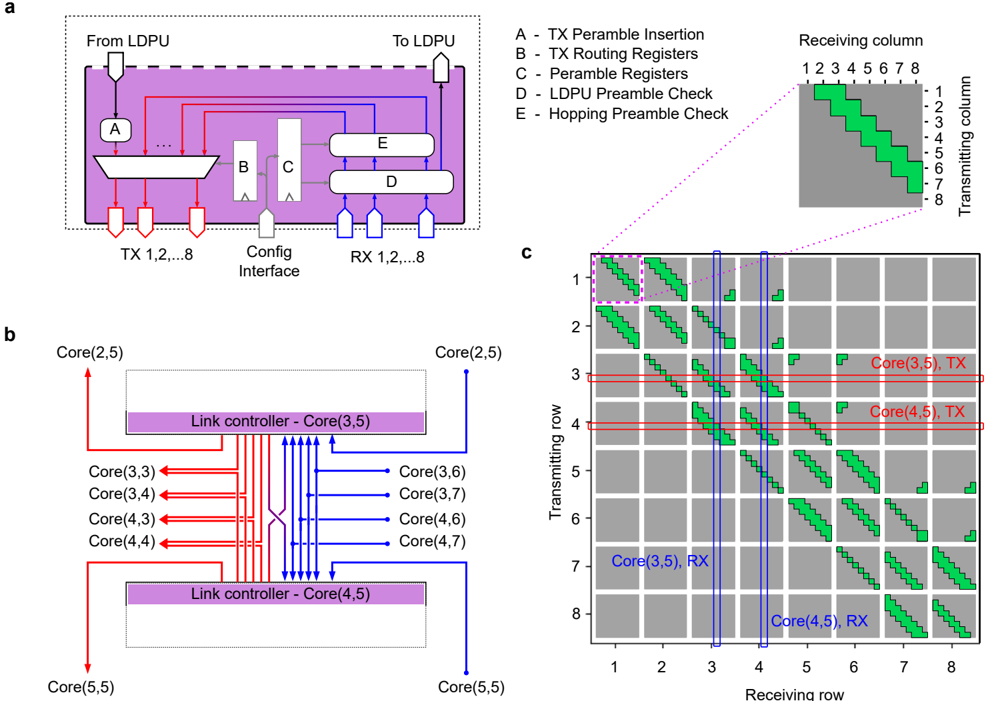
The image presents three interconnected diagrams illustrating a network architecture with components for data transmission, routing, and peramble management. Key elements include LDPU (Link Data Processing Unit), TX/RX units, link controllers, and core nodes. The diagrams emphasize data flow paths, peramble checks, and core-node interactions.
---
### Components/Axes
#### Diagram A (Top-Left)
- **Components**:
- **A**: TX Peramble Insertion (red arrows)
- **B**: TX Routing Registers (red arrows)
- **C**: Peramble Registers (gray arrows)
- **D**: LDPU Peramble Check (blue arrows)
- **E**: Hopping Peramble Check (blue arrows)
- **Flow**:
- Data originates from LDPU (top-left), flows through TX 1-8 (red arrows), and returns via RX 1-8 (blue arrows).
- **Receiving Column Chart** (Top-Right):
- **Axes**:
- X-axis: Transmitting column (1-8)
- Y-axis: Receiving column (1-8)
- **Legend**:
- Green bars: Active data paths
- **Key Feature**: Diagonal green bars indicate hopping patterns.
#### Diagram B (Bottom-Left)
- **Components**:
- **Link Controllers**:
- Core(3,5) (purple box)
- Core(4,5) (purple box)
- **Cores**:
- Core(2,5), Core(3,3), Core(3,4), Core(3,6), Core(3,7), Core(4,3), Core(4,4), Core(4,6), Core(4,7), Core(5,5)
- **Arrows**:
- Red: Data transmission paths
- Blue: Control signals
- **Flow**:
- Data flows between cores via link controllers, with red arrows indicating bidirectional communication.
#### Diagram C (Bottom-Right)
- **Grid Structure**:
- **Axes**:
- X-axis: Receiving row (1-8)
- Y-axis: Transmitting row (1-8)
- **Legend**:
- Green bars: Active data paths
- Red lines: Core(3,5) TX
- Blue lines: Core(4,5) RX
- **Key Features**:
- Red horizontal lines at rows 3 and 4 (Core(3,5) and Core(4,5) TX)
- Blue vertical lines at columns 3 and 4 (Core(3,5) and Core(4,5) RX)
---
### Detailed Analysis
#### Diagram A
- **TX/RX Flow**:
- Data enters from LDPU, passes through TX Peramble Insertion (A), TX Routing Registers (B), and Peramble Registers (C) before reaching TX units.
- Return paths involve LDPU Peramble Check (D) and Hopping Peramble Check (E).
- **Peramble Checks**:
- Red and blue arrows differentiate peramble insertion (TX) from peramble checks (RX).
#### Diagram B
- **Link Controller Function**:
- Core(3,5) and Core(4,5) act as central hubs, managing data flow between adjacent cores.
- Red arrows show data transmission between cores (e.g., Core(3,3) → Core(3,5)).
- Blue arrows indicate control signals (e.g., Core(5,5) → Core(4,5)).
#### Diagram C
- **Data Path Visualization**:
- Green bars form diagonal patterns, suggesting hopping sequences.
- Red lines (Core(3,5) TX) and blue lines (Core(4,5) RX) intersect at specific grid points, indicating targeted data paths.
---
### Key Observations
1. **Peramble Management**:
- Peramble insertion (A) and checks (D, E) are critical for data integrity.
2. **Core Connectivity**:
- Link controllers (Core(3,5), Core(4,5)) centralize data routing.
3. **Grid Patterns**:
- Diagonal green bars in Diagram C suggest dynamic routing or frequency hopping.
4. **Color Consistency**:
- Red (TX) and blue (RX) align with legend labels in all diagrams.
---
### Interpretation
The diagrams depict a distributed network architecture where:
- **LDPU** initiates data transmission, which is routed through TX units and validated via peramble checks.
- **Link controllers** (Core(3,5), Core(4,5)) serve as intermediaries, coordinating data flow between cores.
- The grid in Diagram C visualizes hopping patterns, with Core(3,5) and Core(4,5) acting as focal points for transmission and reception.
**Notable Trends**:
- Core(3,5) and Core(4,5) are central to both data transmission (red lines) and reception (blue lines), suggesting they are critical nodes.
- The diagonal green bars in Diagram C imply a structured hopping mechanism to avoid interference or optimize bandwidth.
This architecture emphasizes redundancy (multiple peramble checks) and efficiency (centralized link controllers), likely designed for high-reliability communication systems.