# Technical Document Extraction: Task Execution State Machines
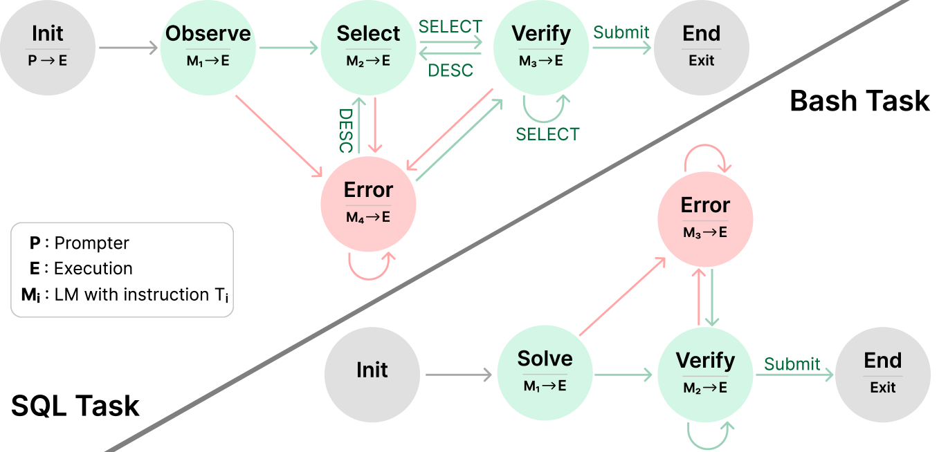
This image illustrates two distinct state machine diagrams representing workflows for automated task completion: a **Bash Task** and a **SQL Task**. The diagram uses color-coded nodes and directed edges to represent states, transitions, and error handling paths.
## 1. Legend and Definitions
Located in the bottom-left quadrant of the image:
* **P**: Prompter
* **E**: Execution
* **Mᵢ**: LM (Language Model) with instruction Tᵢ
* **Arrows/Nodes Color Coding**:
* **Grey**: Initialization or Termination states.
* **Green**: Successful or forward-progress transitions/states.
* **Red**: Error states or transitions triggered by failure.
---
## 2. Bash Task Workflow
The Bash Task is located in the upper-right section of the diagram, separated by a diagonal line.
### Components (Nodes)
1. **Init ($P \to E$):** Grey node. The starting point where the Prompter initiates the Execution environment.
2. **Observe ($M_1 \to E$):** Green node. The first active state where the model observes the environment.
3. **Select ($M_2 \to E$):** Green node. The state where an action or tool is selected.
4. **Verify ($M_3 \to E$):** Green node. The state where the selected action is validated.
5. **Error ($M_4 \to E$):** Red node. A centralized state for handling failures from multiple stages.
6. **End (Exit):** Grey node. The final state of the process.
### Flow and Transitions
* **Success Path:** `Init` $\to$ `Observe` $\to$ `Select` $\xrightarrow{\text{SELECT}}$ `Verify` $\xrightarrow{\text{Submit}}$ `End`.
* **Iterative Loops:**
* Between `Select` and `Verify`: A bidirectional path labeled `SELECT` (forward) and `DESC` (backward).
* Self-loop on `Verify`: Labeled `SELECT`, indicating repeated verification attempts.
* **Error Transitions (Red Arrows):**
* From `Observe` $\to$ `Error`.
* From `Select` $\to$ `Error` (labeled `DESC`).
* From `Verify` $\to$ `Error`.
* **Error Recovery:** A green arrow points from `Error` back to `Verify`.
* **Error Persistence:** A red self-loop exists on the `Error` node.
---
## 3. SQL Task Workflow
The SQL Task is located in the bottom-right section of the diagram.
### Components (Nodes)
1. **Init:** Grey node. The starting point.
2. **Solve ($M_1 \to E$):** Green node. The initial attempt to generate a SQL solution.
3. **Verify ($M_2 \to E$):** Green node. Validation of the generated SQL.
4. **Error ($M_3 \to E$):** Red node. State for handling execution or logic errors.
5. **End (Exit):** Grey node. The final state.
### Flow and Transitions
* **Success Path:** `Init` $\to$ `Solve` $\to$ `Verify` $\xrightarrow{\text{Submit}}$ `End`.
* **Iterative Loops:**
* Self-loop on `Verify`: A green arrow indicating internal re-verification.
* **Error Transitions:**
* From `Solve` $\to$ `Error` (Red arrow).
* From `Verify` $\to$ `Error` (Red arrow).
* **Error Recovery:** A green arrow points from `Error` back down to `Verify`.
* **Error Persistence:** A red self-loop exists on the `Error` node.
---
## 4. Comparative Summary
| Feature | Bash Task | SQL Task |
| :--- | :--- | :--- |
| **Complexity** | Higher (5 active states) | Lower (3 active states) |
| **Initial Step** | Observation ($M_1$) | Solving ($M_1$) |
| **Error Handling** | Centralized $M_4$ node; can return to `Verify` | Centralized $M_3$ node; can return to `Verify` |
| **Key Difference** | Includes a specific `Select` phase with a feedback loop to `Verify`. | Moves directly from `Solve` to `Verify`. |