## Diagram: Grid-Based State Transition Network
### Overview
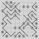
The image depicts a 5x5 grid of interconnected nodes, each labeled with a number (0, 1, 2, or 3). Nodes are connected via directional arrows, suggesting a state transition or workflow system. No explicit legend, axis titles, or labels are present.
### Components/Axes
- **Grid Structure**:
- 5 rows and 5 columns of nodes.
- Each node is a circle containing a single digit (0, 1, 2, or 3).
- Directional arrows connect nodes, indicating transitions.
- **Node Labels**:
- Numbers 0, 1, 2, and 3 are distributed across the grid.
- No additional annotations or legends are visible.
### Detailed Analysis
- **Node Distribution**:
- **0**: Appears in 6 nodes (e.g., (1,1), (1,5), (5,1), (5,5), (3,3), (4,4)).
- **1**: Appears in 5 nodes (e.g., (1,3), (2,2), (3,4), (4,2), (5,3)).
- **2**: Appears in 7 nodes (e.g., (1,2), (2,4), (3,1), (3,5), (4,3), (5,2), (5,4)).
- **3**: Appears in 2 nodes (e.g., (2,3), (4,5)).
- **Connections**:
- Arrows form a cyclic pattern: **0 → 1 → 2 → 3 → 0**.
- Some nodes have multiple outgoing arrows (e.g., node 2 at (3,1) connects to 3 and 0).
- Arrows are unidirectional, with no bidirectional or self-loops.
### Key Observations
1. **Cyclic Flow**: The primary pattern is a closed loop (0→1→2→3→0), suggesting a repeating process.
2. **Branching Paths**: Nodes like 2 (e.g., at (3,1)) have multiple outgoing arrows, indicating decision points or parallel transitions.
3. **0 as Terminal/Initial State**: Nodes labeled 0 are positioned at grid corners and edges, potentially marking start/end states.
4. **Sparse 3 Nodes**: Only two nodes labeled 3 exist, both connected to 0, reinforcing the cycle’s closure.
### Interpretation
This diagram likely represents a **state machine** or **workflow** with four states (0–3) and transitions between them. The cyclic nature implies a repetitive process, while branching paths (e.g., node 2 connecting to both 3 and 0) suggest conditional logic or parallel execution. The placement of 0s at grid extremities may indicate boundary conditions or reset points. The absence of a legend or labels limits contextual interpretation, but the numerical labels and directional arrows strongly suggest a computational or algorithmic model.