## Diagram: Dual Cyclical Process Flow
### Overview
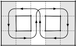
The image displays a technical diagram illustrating two parallel, cyclical processes or loops. The diagram is presented in a monochrome (black and white) style on a light gray background with a faint dashed grid overlay. There is no textual information, labels, or numerical data present in the image.
### Components/Axes
* **Primary Structure:** A large, solid black rectangle forms the outer boundary of the diagram.
* **Internal Elements:** Two identical, vertically oriented rectangular loops are positioned side-by-side within the outer rectangle. They are separated by a central vertical axis.
* **Flow Indicators:** Each loop is defined by a continuous black line with arrowheads indicating direction. The arrows show a clockwise flow for the left loop and a counterclockwise flow for the right loop.
* **Background:** A light gray fill with a grid of dashed lines (vertical and horizontal) is visible behind the main diagram elements.
### Detailed Analysis
* **Left Loop (Clockwise Flow):**
* The path starts at the top-left corner of the inner rectangle.
* An arrow points right along the top edge.
* An arrow points down along the right edge.
* An arrow points left along the bottom edge.
* An arrow points up along the left edge, completing the cycle.
* **Right Loop (Counterclockwise Flow):**
* The path starts at the top-right corner of the inner rectangle.
* An arrow points left along the top edge.
* An arrow points down along the left edge.
* An arrow points right along the bottom edge.
* An arrow points up along the right edge, completing the cycle.
* **Spatial Relationship:** The two loops are mirror images of each other across the central vertical axis. Their top and bottom edges are horizontally aligned.
### Key Observations
1. **Symmetry:** The diagram exhibits perfect bilateral symmetry. The right loop is a precise mirror reflection of the left loop.
2. **Directional Contrast:** The core distinction between the two components is their flow direction: clockwise vs. counterclockwise.
3. **Closed Systems:** Both loops are closed, suggesting continuous, self-contained processes or cycles.
4. **Absence of Text:** The diagram is purely symbolic. It contains zero alphanumeric characters, labels, titles, or annotations.
### Interpretation
This diagram is a conceptual representation of two opposing or complementary cyclical systems. The lack of text makes it a universal template, applicable to various contexts where dual, mirrored processes are relevant.
* **Potential Meanings:** It could represent:
* **Feedback Loops:** A positive and a negative feedback loop in a system.
* **Process Flows:** Two stages of a manufacturing or data processing cycle that operate in reverse sequence.
* **Logical Operations:** A visual metaphor for opposing logical states or operations.
* **Physical Systems:** Counter-rotating mechanisms or balanced forces.
* **Relationship Between Elements:** The central placement and symmetry imply the two processes are of equal importance and operate in tandem or balance. The shared outer boundary suggests they exist within a single larger system or environment.
* **Notable Anomaly:** The primary "anomaly" is the complete absence of explanatory text, which forces the viewer to interpret the diagram based solely on its geometric and directional properties. This makes it a powerful but ambiguous symbol.
**Conclusion:** The image contains no extractable textual data or quantitative information. Its entire informational content is conveyed through the spatial arrangement, shape, and directional arrows of its graphical components, depicting two symmetrical, opposing cyclical flows.