## Image Comparison: Rendering Techniques
### Overview
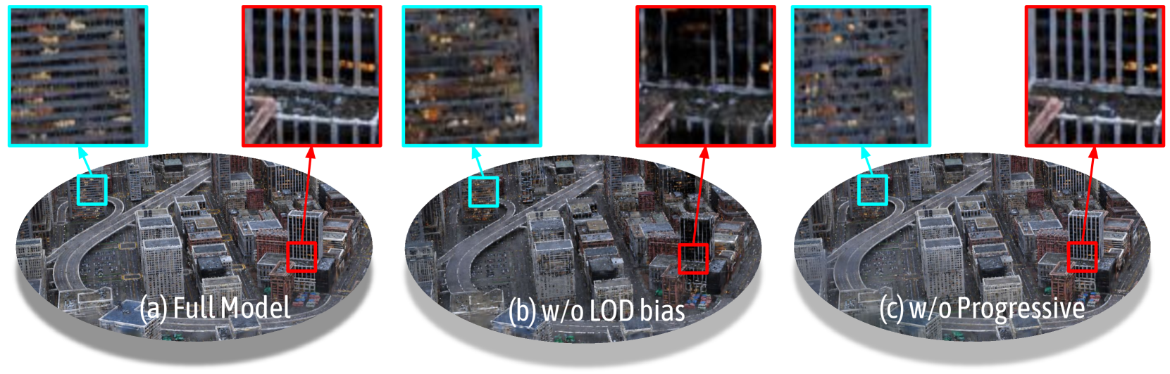
The image presents a visual comparison of three different rendering techniques applied to a cityscape model. Each technique is showcased with a wide view of the city and two zoomed-in views, one highlighted with a cyan box and the other with a red box. The techniques being compared are: (a) Full Model, (b) w/o LOD bias, and (c) w/o Progressive.
### Components/Axes
* **Titles:**
* (a) Full Model
* (b) w/o LOD bias
* (c) w/o Progressive
* **Zoomed-in Views:** Each rendering technique has two zoomed-in views associated with it. One is highlighted with a cyan box and the other with a red box.
### Detailed Analysis or Content Details
* **(a) Full Model:**
* The wide view shows a detailed cityscape with numerous buildings and roads.
* The cyan-boxed zoomed-in view shows a section of a building with visible window details.
* The red-boxed zoomed-in view shows a section of a building with vertical lines, possibly representing window frames or architectural details.
* **(b) w/o LOD bias:**
* The wide view shows a cityscape that appears slightly less detailed than the "Full Model" version.
* The cyan-boxed zoomed-in view shows a section of a building with blurred window details.
* The red-boxed zoomed-in view shows a section of a building with less defined vertical lines compared to the "Full Model" version.
* **(c) w/o Progressive:**
* The wide view shows a cityscape that appears similar in detail to the "Full Model" version.
* The cyan-boxed zoomed-in view shows a section of a building with visible window details, similar to the "Full Model" version.
* The red-boxed zoomed-in view shows a section of a building with vertical lines, similar to the "Full Model" version.
### Key Observations
* The "Full Model" rendering appears to have the highest level of detail in both the wide view and the zoomed-in views.
* The "w/o LOD bias" rendering seems to have reduced detail, particularly noticeable in the zoomed-in views where the window details are blurred and the vertical lines are less defined.
* The "w/o Progressive" rendering appears to maintain a similar level of detail to the "Full Model" rendering.
### Interpretation
The image demonstrates the impact of different rendering techniques on the visual quality of a cityscape model. The "Full Model" likely represents a baseline with all rendering features enabled. Removing the LOD (Level of Detail) bias results in a noticeable reduction in detail, suggesting that LOD bias is important for maintaining visual fidelity, especially in zoomed-in views. Removing the "Progressive" rendering feature seems to have little to no impact on the final image quality, at least in the areas highlighted. The comparison suggests that LOD bias plays a more significant role in rendering detail than the "Progressive" feature in this specific scenario.