## Diagram: Synthetic Cell Interface and Processor System
### Overview
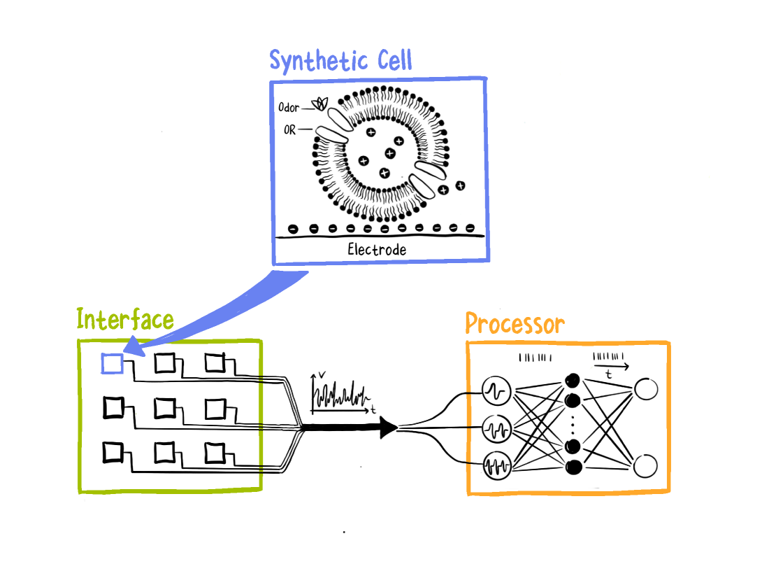
The image depicts a conceptual technical system integrating a **Synthetic Cell**, an **Interface**, and a **Processor**. The components are interconnected, suggesting a flow of information or signals between them. The diagram uses color-coded sections (blue, green, orange) to differentiate components and includes labeled elements with directional arrows.
### Components/Axes
1. **Synthetic Cell (Top Section)**
- **Labels**:
- "Synthetic Cell" (title)
- "odor" (with a flower-like symbol)
- "OR" (Olfactory Receptor, labeled with a circular structure)
- "Electrode" (labeled at the bottom of the cell)
- **Visual Elements**:
- A circular structure with radiating filaments (possibly representing cellular membranes or signaling structures).
- Positive (+) and negative (-) charges distributed within the cell.
- A horizontal line of alternating positive and negative charges at the bottom (likely representing an electrode interface).
2. **Interface (Middle-Left Section)**
- **Labels**:
- "Interface" (title)
- **Visual Elements**:
- A grid of 8 squares (4 rows, 2 columns) with a blue arrow pointing to the Synthetic Cell.
- The squares are connected to the Synthetic Cell via a thick blue line, indicating signal transmission.
3. **Processor (Right Section)**
- **Labels**:
- "Processor" (title)
- **Visual Elements**:
- A neural network diagram with interconnected nodes (circles and lines).
- Input signals (wavy lines) enter the network from the Interface.
- Output signals (arrows) exit the network, suggesting processed data.
### Detailed Analysis
- **Synthetic Cell**:
- The cell is depicted as a biological or bio-inspired system with sensory capabilities (odor detection via "OR").
- The electrode at the bottom suggests a connection to external systems for signal transmission.
- Positive/negative charges imply electrochemical or ionic interactions.
- **Interface**:
- The grid of squares may represent input data or sensor outputs.
- The blue arrow and line indicate a direct connection to the Synthetic Cell, implying data or signal flow from the Interface to the cell.
- **Processor**:
- The neural network (orange section) processes input signals (wavy lines) and produces outputs (arrows).
- The complexity of the network suggests advanced computational capabilities, possibly for pattern recognition or decision-making.
### Key Observations
- **Flow of Information**:
- The Interface acts as a bridge between the Synthetic Cell and the Processor, transmitting signals from the cell to the computational system.
- The Synthetic Cell’s "odor" and "OR" components suggest it detects environmental stimuli, which are then processed by the neural network.
- **Color Coding**:
- Blue (Interface) and orange (Processor) highlight the separation of functional modules.
- The Synthetic Cell (black/white) is visually distinct, emphasizing its biological or hybrid nature.
- **No Numerical Data**:
- The diagram lacks charts, axes, or numerical values. It focuses on structural and functional relationships rather than quantitative metrics.
### Interpretation
This diagram illustrates a **bio-inspired computational system** where a Synthetic Cell (potentially a bioengineered or artificial cell) interacts with an Interface to transmit sensory data (e.g., odor detection) to a Processor (a neural network). The system likely serves as a model for integrating biological sensing with artificial intelligence, enabling real-time data processing and decision-making.
- **Biological-Computational Integration**:
- The Synthetic Cell’s "OR" and electrode suggest it mimics biological sensory systems, while the Processor represents artificial intelligence.
- The Interface ensures seamless communication between the two domains.
- **Potential Applications**:
- Environmental monitoring (e.g., detecting pollutants via odor sensors).
- Medical diagnostics (e.g., identifying biomarkers through synthetic cell responses).
- Robotics or autonomous systems requiring sensory input and adaptive processing.
- **Notable Design Choices**:
- The use of a neural network in the Processor implies the system is designed for complex, non-linear data processing.
- The grid in the Interface may represent modular input handling, allowing parallel processing of multiple signals.
This diagram emphasizes the synergy between biological and computational systems, highlighting a framework for future technologies that bridge the gap between living organisms and artificial intelligence.