## Diagram: Transient Execution Attack Process
### Overview
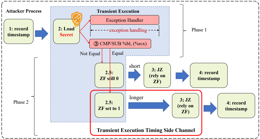
The image illustrates a transient execution attack process, outlining the steps an attacker might take to exploit vulnerabilities related to transient execution. The process is divided into two phases and highlights the role of exception handling and timing side channels.
### Components/Axes
* **Attacker Process:** The overall process initiated by the attacker.
* **Transient Execution:** The vulnerable execution environment.
* **Phase 1:** The initial phase involving loading a secret and exception handling.
* **Phase 2:** The phase where the attacker leverages the Zero Flag (ZF) and timing side channels.
* **Nodes:** Represented as rounded rectangles, each containing a step number and a description.
* **Arrows:** Indicate the flow of execution.
* **Decision Points:** Based on equality checks, leading to different execution paths.
* **Transient Execution Timing Side Channel:** Highlighted with a red box, indicating a critical area of exploitation.
### Detailed Analysis or ### Content Details
**Attacker Process:**
1. **1: record timestamp:** The attacker records a timestamp.
2. **2: Load Secret:** The attacker loads a secret. This step is associated with an icon resembling a shield with a keyhole, suggesting a protected resource.
**Transient Execution (Phase 1):**
* **Exception Handler:** If an exception occurs during the loading of the secret, the process goes to the exception handler. The text "exception handling" is written between two dashed lines, indicating the scope of the exception handling.
* **3 CMP/SUB %bl, (%rcx):** A comparison or subtraction operation is performed.
* **Decision Point:** The result of the comparison determines the execution path.
* **Not Equal:** If the comparison is not equal, the process moves to "2.5: ZF still 0".
* **Equal:** If the comparison is equal, the process moves to "2.5: ZF set to 1".
**Phase 2:**
* **2.5: ZF still 0:** The Zero Flag (ZF) remains 0.
* **short:** This path is labeled "short".
* **3; JZ (rely on ZF):** A jump-if-zero instruction is executed, relying on the ZF.
* **4: record timestamp:** A timestamp is recorded.
* **2.5: ZF set to 1:** The Zero Flag (ZF) is set to 1.
* **longer:** This path is labeled "longer".
* **3; JZ (rely on ZF):** A jump-if-zero instruction is executed, relying on the ZF.
* **4: record timestamp:** A timestamp is recorded.
**Transient Execution Timing Side Channel:**
* The path where ZF is set to 1 is enclosed in a red box labeled "Transient Execution Timing Side Channel". This indicates that the timing difference between the "ZF still 0" and "ZF set to 1" paths can be exploited to leak information.
### Key Observations
* The process involves loading a secret and performing operations that can lead to exceptions.
* The Zero Flag (ZF) plays a crucial role in determining the execution path.
* The timing difference between different execution paths can be exploited as a side channel.
### Interpretation
The diagram illustrates a transient execution attack where an attacker attempts to extract a secret by exploiting timing differences in the execution path. The attacker first loads a secret, which may trigger an exception. The subsequent comparison operation and the state of the Zero Flag (ZF) determine the execution path. The timing difference between the paths where ZF is still 0 and ZF is set to 1 can be measured and used to infer information about the secret. The "Transient Execution Timing Side Channel" highlights the vulnerability, indicating that the attacker can potentially learn about the secret by analyzing the execution time of different code paths. The diagram demonstrates how subtle differences in execution can be exploited to compromise security.