## Diagram: Transient Execution Timing Side-Channel Attack Flowchart
### Overview
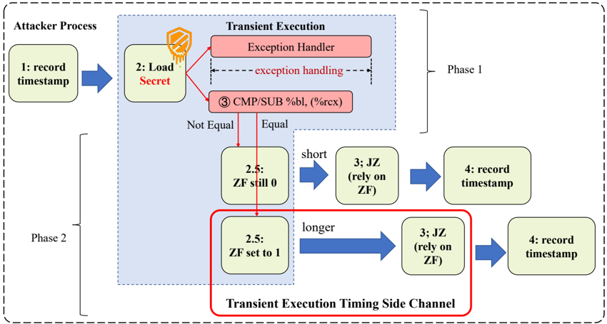
The image is a technical flowchart illustrating a two-phase side-channel attack process that exploits transient execution (likely a speculative or out-of-order execution vulnerability) to leak secret data via timing differences. The diagram details the sequence of operations performed by an attacker process and the microarchitectural events within a CPU's transient execution engine.
### Components/Axes
The diagram is structured into three main visual regions:
1. **Attacker Process (Left Column):** A vertical sequence of green boxes representing the attacker's software steps.
2. **Transient Execution (Central Blue Box):** A shaded region representing internal CPU operations, containing red and green boxes.
3. **Phase Labels:** "Phase 1" (top) and "Phase 2" (bottom) are labeled on the right side, bracketing the relevant steps.
**Key Textual Elements & Labels:**
* **Attacker Process Box:** Contains the text "Attacker Process".
* **Transient Execution Box:** Contains the text "Transient Execution".
* **Phase Labels:** "Phase 1" and "Phase 2".
* **Red Highlight Box:** A red-bordered box at the bottom is labeled "Transient Execution Timing Side Channel".
* **Instruction Text:** "CMP/SUB %bl, (%rcx)" (x86 assembly instruction).
* **Condition Labels:** "Not Equal" and "Equal" (arrows from the CMP/SUB box).
* **Flag State Labels:** "ZF still 0" and "ZF set to 1" (where ZF stands for Zero Flag).
* **Timing Descriptors:** "short" and "longer" (describing the duration of the subsequent JZ instruction).
* **Action Labels:** "record timestamp", "Load Secret", "exception handling", "JZ (rely on ZF)".
### Detailed Analysis
The attack flow is segmented into two distinct phases:
**Phase 1: Secret Load and Exception Handling**
1. **Step 1 (Attacker):** "record timestamp" - The attacker process begins by taking a timing measurement.
2. **Step 2 (Attacker):** "Load Secret" - The attacker attempts to access a secret memory location. This action is shown triggering events within the Transient Execution domain.
3. **Inside Transient Execution:**
* The "Load Secret" operation leads to an **"Exception Handler"** (red box). A dashed arrow labeled "exception handling" indicates this process takes some time.
* Concurrently or as part of the exception, the instruction **"③ CMP/SUB %bl, (%rcx)"** is executed. This compares the value in register `%bl` with the value at the memory address in `%rcx`.
**Phase 2: Timing Side-Channel Exploitation**
The outcome of the CMP/SUB instruction determines the path in Phase 2, creating a timing difference.
* **Path A (Not Equal):**
* The Zero Flag (ZF) is **"still 0"** (Step 2.5).
* This leads to a **"short"** execution path for the next instruction, **"③ JZ (rely on ZF)"** (Jump if Zero). Since ZF=0, the jump is not taken quickly.
* The attacker then executes **"④ record timestamp"**.
* **Path B (Equal):**
* The Zero Flag (ZF) is **"set to 1"** (Step 2.5).
* This leads to a **"longer"** execution path for the **"③ JZ (rely on ZF)"** instruction. Since ZF=1, the jump is taken, which involves a pipeline flush or other microarchitectural delay, making this path measurably slower.
* The attacker then executes **"④ record timestamp"**.
The red box explicitly highlights that the difference in duration between the "short" and "longer" paths for the JZ instruction constitutes the **"Transient Execution Timing Side Channel"**.
### Key Observations
1. **Causal Chain:** The diagram explicitly links a architectural event (secret-dependent comparison) to a microarchitectural side effect (exception handling, flag setting) and finally to a measurable software observable (timing difference).
2. **Critical Dependency:** The entire side channel hinges on the **JZ instruction's execution time being dependent on the Zero Flag's state**, which was set by a secret-dependent operation (CMP/SUB) that occurred during transient execution.
3. **Spatial Layout:** The "Transient Execution Timing Side Channel" label is placed at the bottom, directly encompassing the two divergent paths (ZF still 0 / ZF set to 1) and their consequences, emphasizing this is the core leakage mechanism.
4. **Color Coding:** Red is used for components related to the exception and the side-channel itself, drawing attention to the anomalous or security-critical parts of the flow. Green represents standard attacker-controlled steps.
### Interpretation
This flowchart provides a mechanistic explanation for a class of microarchitectural side-channel attacks (akin to Spectre or similar transient execution attacks). It demonstrates how an attacker can craft a situation where a secret value influences the internal state of the CPU (the Zero Flag) during a brief window of speculative or erroneous execution. Although the incorrect execution is eventually rolled back, the *timing* of subsequent instructions is affected by this internal state, creating a covert channel.
The "Load Secret" step is the attack's target. The "CMP/SUB" instruction is the probe that encodes the secret into the ZF. The "JZ" instruction is the sensor that decodes the ZF's state into a timing difference. The two "record timestamp" steps are the measurement points that allow the attacker to infer the secret by statistically analyzing many runs, distinguishing between the "short" and "longer" execution times.
The diagram's value is in isolating the precise microarchitectural event (the variable-latency JZ) that bridges the gap between a secret CPU state and an observable output, which is the fundamental challenge in designing defenses against such attacks.