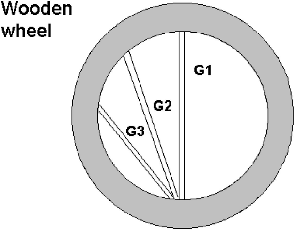
## Diagram: Wooden Wheel Structure
### Overview
The image depicts a simplified technical diagram of a wooden wheel. The wheel is circular with a gray outer rim and a white inner hub. Three radial spokes labeled **G1**, **G2**, and **G3** divide the wheel into three uneven sections. The text "Wooden wheel" is positioned at the top-left corner of the diagram.
### Components/Axes
- **Wheel Structure**:
- **Outer Rim**: Gray circular band.
- **Inner Hub**: White circular area.
- **Spokes**: Three radial lines labeled **G1**, **G2**, and **G3**.
- **Labels**:
- **G1**: Vertical spoke on the right side.
- **G2**: Diagonal spoke from top-right to bottom-left.
- **G3**: Diagonal spoke from top-left to bottom-right.
- **Text**: "Wooden wheel" (top-left corner).
### Detailed Analysis
- **Spoke Placement**:
- **G1** is positioned vertically at the 3 o’clock position.
- **G2** spans from the 1 o’clock to 7 o’clock position.
- **G3** spans from the 11 o’clock to 5 o’clock position.
- **Color Coding**:
- The outer rim is uniformly gray.
- The inner hub is white, with no additional shading or gradients.
- **Textual Elements**:
- "Wooden wheel" is in black, sans-serif font, left-aligned.
- Labels **G1**, **G2**, and **G3** are in bold black text, placed near their respective spokes.
### Key Observations
1. The spokes are not evenly spaced, suggesting a non-symmetrical design.
2. The labels **G1**, **G2**, and **G3** are unambiguous and directly associated with their spokes.
3. No numerical values, scales, or additional annotations are present.
### Interpretation
This diagram likely represents a conceptual or schematic representation of a wooden wheel, emphasizing its structural components rather than functional dynamics. The labels **G1–G3** may denote specific stress points, load-bearing elements, or assembly instructions in an engineering context. The absence of numerical data or motion indicators suggests the diagram is static, focusing on geometry rather than performance metrics. The uneven spoke spacing could imply a custom or non-standard wheel design, requiring further context for precise interpretation.
**Note**: The image contains no numerical data, trends, or quantitative information. All descriptions are based on visible textual and structural elements.