## Diagram: Hand Pose Estimation
### Overview
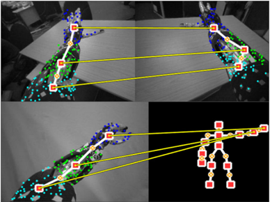
The image shows a diagram illustrating hand pose estimation. It consists of four sub-images arranged in a 2x2 grid. The top two sub-images show a robotic hand in different poses, with overlaid markers and a skeletal representation. The bottom-left sub-image shows another pose of the robotic hand with similar overlays. The bottom-right sub-image displays a simplified skeletal model of a hand. Yellow lines connect corresponding points between the real hand images and the skeletal model.
### Components/Axes
* **Top-Left Sub-image:** A grayscale image of a robotic hand resting on a table. The hand is marked with blue, green, and cyan dots. A white line connects key points, which are marked with red squares and orange circles.
* **Top-Right Sub-image:** Similar to the top-left, but the hand is in a different pose. The same color scheme for markers and skeletal representation is used.
* **Bottom-Left Sub-image:** Another grayscale image of the robotic hand in a different pose, with the same marker and skeletal representation scheme.
* **Bottom-Right Sub-image:** A black background with a simplified skeletal model of a hand. The joints are represented by red squares, and the bones are represented by orange circles.
### Detailed Analysis or ### Content Details
* **Robotic Hand:** The robotic hand appears to be a prosthetic or experimental device. It has multiple joints and a complex structure.
* **Markers:** The blue, green, and cyan dots likely represent feature points detected by a computer vision algorithm.
* **Skeletal Representation:** The white line connecting key points represents the estimated pose of the hand. The red squares and orange circles mark the joint locations.
* **Yellow Lines:** The yellow lines connect corresponding joints between the real hand images and the simplified skeletal model. This visually demonstrates the mapping between the detected features and the skeletal representation.
### Key Observations
* The diagram demonstrates a system for estimating the pose of a robotic hand using computer vision techniques.
* The markers and skeletal representation are overlaid on the real hand images to show the accuracy of the pose estimation.
* The simplified skeletal model provides a clear representation of the hand's pose.
### Interpretation
The diagram illustrates a hand pose estimation system. The system uses computer vision algorithms to detect feature points on the hand and then maps these points to a simplified skeletal model. The yellow lines demonstrate the correspondence between the detected features and the skeletal representation. This type of system could be used in robotics, virtual reality, and other applications where it is necessary to track the pose of a hand.