## Kinematic Diagram of Robotic Arm with Marker Placement
### Overview
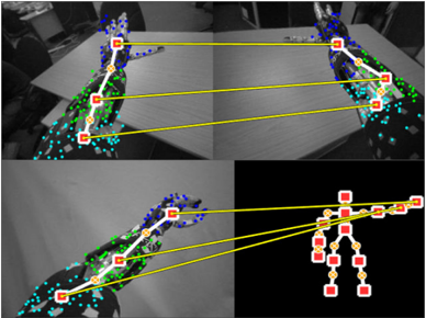
The image presents a multi-view technical diagram of a robotic arm system with embedded motion tracking markers. It combines real-world imagery with schematic annotations to illustrate joint configurations and marker placement. Four quadrants show different perspectives: top-left (wide-angle), top-right (angled view), bottom-left (close-up), and bottom-right (simplified schematic).
### Components/Axes
- **Legend** (bottom-right corner):
- Red squares: Motion tracking markers
- Yellow lines: Structural connections between components
- Blue dots: Joint centers
- **Arm Segments** (labeled in schematic):
- Wrist (bottom segment)
- Forearm (middle segment)
- Elbow (joint between forearm and upper arm)
- Upper arm (proximal segment)
- Shoulder (base joint)
- End-effector (tool attachment point)
### Detailed Analysis
1. **Marker Placement**:
- Red squares are positioned at:
- Shoulder joint (base)
- Elbow joint
- Wrist joint
- End-effector tip
- Additional blue dots mark secondary joint centers along the arm's length.
2. **Structural Connections**:
- Yellow lines form a hierarchical tree structure:
- Base connection (shoulder to upper arm)
- Elbow joint connection
- Wrist joint connection
- End-effector attachment
3. **View Variations**:
- Top-left: Full arm extension with markers visible against workspace background
- Top-right: Angled view showing marker alignment with workspace plane
- Bottom-left: Close-up of wrist/forearm segment with detailed marker spacing
- Bottom-right: Simplified schematic with color-coded components and connection lines
### Key Observations
- Markers are consistently placed at joint centers and end-effector, suggesting focus on kinematic analysis
- Yellow lines maintain consistent spacing between markers, indicating standardized measurement intervals
- Bottom-right schematic uses identical color coding to reinforce component relationships
- No numerical values or axis scales present in the image
### Interpretation
This diagram demonstrates a motion capture system for robotic arm analysis. The marker placement at critical joints enables:
1. **Kinematic Calibration**: Precise measurement of joint angles and link lengths
2. **Path Planning**: Visualization of end-effector trajectory through marker tracking
3. **Error Detection**: Identification of positional discrepancies between planned and actual movements
The color-coded legend ensures unambiguous interpretation of components, while the multi-view presentation allows analysis from different operational perspectives. The absence of numerical data suggests this is a conceptual diagram rather than empirical measurement results, focusing on system architecture rather than performance metrics.