## Diagram: Modular Block Pathway System
### Overview
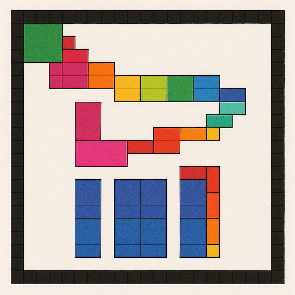
The image displays a schematic diagram of interconnected colored blocks arranged on a white background, enclosed within a black border composed of small, uniform squares. The diagram appears to represent a conceptual model of pathways, connections, or a modular system, possibly for illustrating flow, network topology, or a puzzle-like structure. There is no textual information, labels, axes, or legends present. The information is conveyed entirely through the spatial arrangement, color, and relative positioning of the geometric blocks.
### Components
The diagram consists of the following visual elements:
1. **Border:** A continuous frame made of small, dark gray/black squares, creating a grid-like boundary around the entire composition.
2. **Blocks:** The primary elements are rectangular and square blocks of solid colors. Each block is subdivided by thin black lines into smaller, uniform square units, giving them a tiled or modular appearance.
3. **Color Palette:** The blocks use a distinct set of colors: green, red, pink/magenta, orange, yellow, lime green, blue, teal, and dark blue.
4. **Spatial Layout:** The blocks are arranged in three primary groupings or pathways within the white interior space.
### Detailed Analysis
The blocks are organized into three distinct, non-overlapping pathways or structures:
**1. Upper Diagonal Pathway (Top-Left to Mid-Right):**
* **Starts** at the top-left with a large **green** square block (approx. 2x2 units).
* Connects diagonally downward to the right through a sequence of blocks:
* A **red** block (1x1 unit).
* A **pink** block (2x2 units).
* An **orange** block (2x2 units).
* A **yellow** block (2x2 units).
* A **lime green** block (2x2 units).
* A **blue** block (2x2 units).
* Ends with a **dark blue** block (2x2 units) at the mid-right edge of the diagram.
* **Trend:** This pathway forms a descending staircase pattern from the upper-left corner towards the center-right.
**2. Middle Horizontal & Vertical Pathway (Center-Left to Center-Right):**
* **Starts** below the upper pathway with a vertical **pink** block (2x1 units).
* Connects to a horizontal **pink** block (3x2 units) extending to the right.
* Continues rightward through:
* A **red** block (2x2 units).
* An **orange** block (2x2 units).
* A **yellow** block (2x2 units).
* Turns upward with a **teal** block (2x2 units).
* Ends with a **green** block (2x2 units) positioned above the teal block.
* **Trend:** This pathway forms a roughly "L" or hook shape, moving horizontally right and then vertically up.
**3. Lower Vertical Structures (Bottom-Left to Bottom-Right):**
These are three separate, vertical columnar structures.
* **Left Column:** A single vertical **blue** column (2 units wide x 6 units high).
* **Center Column:** A wider vertical **blue** structure (4 units wide x 6 units high), appearing as a 2x3 grid of larger blue blocks.
* **Right Column:** A composite vertical structure (2 units wide x 6 units high).
* The left half is a continuous **blue** column.
* The right half is segmented by color from top to bottom: **red** (2 units), **orange** (2 units), **yellow** (2 units).
### Key Observations
* **No Text or Data:** The image contains zero textual information, numerical data, labels, or legends. It is a purely visual, abstract diagram.
* **Color as Identifier:** Color is the sole differentiator between block types or components. There is no explicit key explaining what each color represents.
* **Modular Design:** All blocks are built from a common grid of smaller squares, suggesting a system based on standardized units.
* **Disconnected Pathways:** The three main groupings (Upper, Middle, Lower) do not appear to be physically connected to each other. They exist as separate entities within the frame.
* **Spatial Grounding:** The upper pathway occupies the top third, the middle pathway the central third, and the lower structures the bottom third of the diagram's interior space.
### Interpretation
This diagram is an abstract representation of a system, not a chart of empirical data. Its meaning is open to interpretation, but the visual language suggests several possibilities:
1. **Network or Flow Diagram:** The colored blocks could represent nodes or modules, and their adjacency implies a connection or pathway for information, material, or process flow. The different colors might signify different types of nodes, functions, or states.
2. **Puzzle or Game Board:** The arrangement resembles a puzzle where the goal might be to connect specific colored blocks or navigate a path. The separate lower structures could be starting points, endpoints, or resource pools.
3. **Conceptual Model of Organization:** It could illustrate concepts like departmental structures (colors as teams), workflow stages, or data architecture, where the spatial layout shows relationships and hierarchies.
4. **Emphasis on Modularity and Composition:** The consistent use of a grid-based building block highlights themes of construction, scalability, and systematic design. The separation of the three pathways might indicate independent subsystems within a larger whole.
**Notable Anomaly:** The lack of any connecting lines between the three major pathways is significant. If this is meant to represent a single integrated system, the diagram is incomplete. If it represents three independent systems, their juxtaposition within the same frame invites comparison or suggests they are part of a larger, unseen context.
**Conclusion:** The image provides structural and relational information but no factual data. To extract specific meaning, one would need external context explaining the symbolism of the colors and the intended purpose of the diagram (e.g., "Blue blocks represent databases, red blocks represent user inputs..."). Without that, it remains a well-defined but semantically open schematic of modular components.