# Technical Document Extraction: Symbolic Knowledge Integration in LLMs
## Diagram Overview
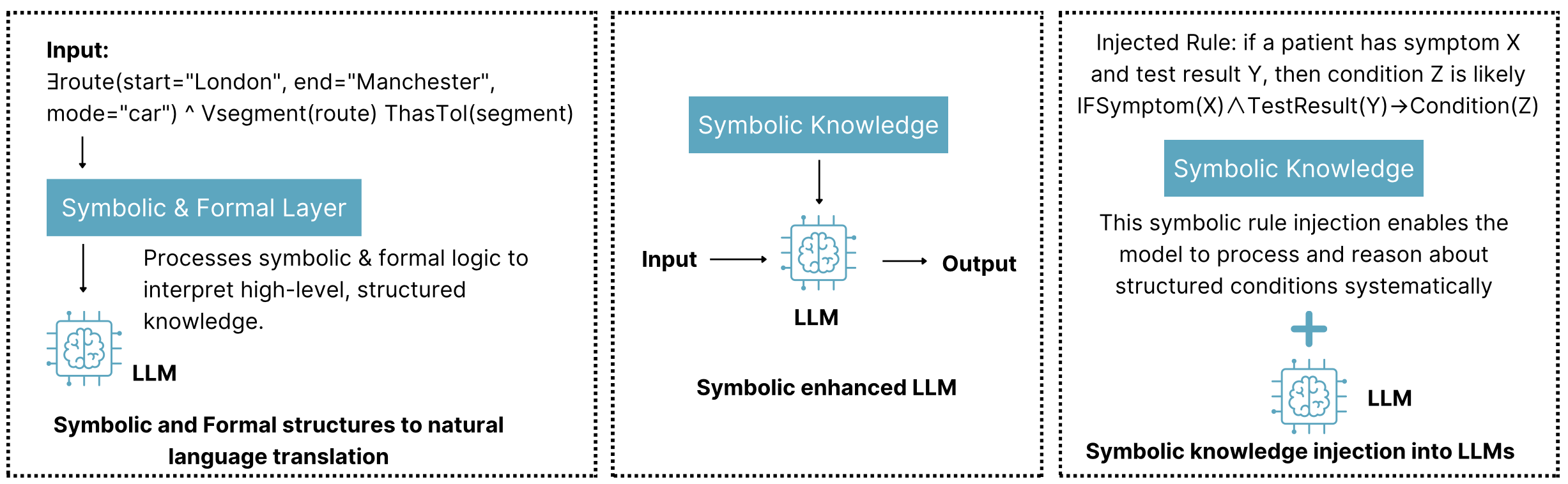
The image presents a three-panel technical architecture diagram illustrating the integration of symbolic knowledge with Large Language Models (LLMs). Each panel demonstrates a distinct phase of processing and knowledge injection.
---
### Panel 1: Input Processing
**Components:**
1. **Input Specification**
- Query: `Eroute(start="London", end="Manchester", mode="car") ^ Vsegment(route) ThisTol(segment)`
- Format: Logical expression combining route parameters and segment validation
2. **Symbolic & Formal Layer**
- Function: Translates natural language input into structured knowledge
- Process: Applies symbolic logic to interpret high-level, structured knowledge
- Output: Natural language translation
3. **LLM Interface**
- Representation: Brain icon with electrical connectors
- Role: Processes translated knowledge for response generation
**Key Text:**
> "Symbolic and Formal structures to natural language translation"
---
### Panel 2: Core LLM Architecture
**Components:**
1. **Input/Output Flow**
- Input → LLM → Output
- Symbolic Knowledge: Blue knowledge box with brain icon
2. **Symbolic Enhanced LLM**
- Architecture: Brain icon with electrical connectors
- Function: Processes input through symbolic knowledge integration
**Key Text:**
> "Symbolic enhanced LLM"
---
### Panel 3: Knowledge Injection
**Components:**
1. **Injected Rule**
- Format: Formal logic expression
- Example: `IF Symptom(X) ∧ TestResult(Y) → Condition(Z)`
- Meaning: "If a patient has symptom X and test result Y, then condition Z is likely"
2. **Symbolic Knowledge Integration**
- Visual: Plus sign connecting knowledge box to LLM
- Function: Enables systematic reasoning about structured conditions
**Key Text:**
> "This symbolic rule injection enables the model to process and reason about structured conditions systematically"
---
### Technical Specifications
- **Color Coding:**
- Blue: Symbolic knowledge components (knowledge boxes, brain icons)
- Black: Text and structural elements
- White: Background
- **Spatial Grounding:**
- Panel 1: [x=0, y=0] to [x=1, y=1]
- Panel 2: [x=1, y=0] to [x=2, y=1]
- Panel 3: [x=2, y=0] to [x=3, y=1]
- **Legend (Implicit):**
- Brain icon: Represents LLM components
- Electrical connectors: Denote knowledge integration points
- Plus sign: Indicates knowledge injection
---
### Process Flow Summary
1. **Input Transformation** (Panel 1)
- Natural language query → Structured knowledge representation
2. **Core Processing** (Panel 2)
- LLM enhanced with symbolic knowledge for improved reasoning
3. **Knowledge Injection** (Panel 3)
- Formal rules injected to enable systematic condition reasoning
---
### Key Technical Concepts
1. **Symbolic Knowledge**: High-level, structured information processed through formal logic
2. **LLM Integration**: Combines neural network processing with symbolic reasoning
3. **Rule Injection**: Formal logic expressions embedded to enhance model capabilities
4. **Condition Reasoning**: Systematic processing of medical/technical conditions through injected rules
---
### Limitations
- No numerical data or statistical trends present
- Focus on architectural components rather than performance metrics
- No explicit error handling or failure modes depicted
This diagram illustrates a knowledge-enhanced LLM architecture where symbolic reasoning capabilities are systematically integrated with neural network processing to improve structured knowledge handling.