\n
## Diagram: Bidirectional Processing Architecture
### Overview
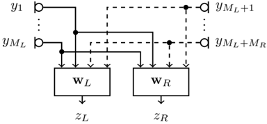
The image depicts a diagram illustrating a bidirectional processing architecture, likely within a neural network or similar computational model. It shows two processing blocks, labeled W<sub>L</sub> and W<sub>R</sub>, receiving input from a sequence of data points (y<sub>1</sub> to y<sub>M<sub>L</sub></sub>) and producing outputs (z<sub>L</sub> and z<sub>R</sub>). The diagram highlights connections between the input sequence and both processing blocks, as well as connections between the blocks themselves via dashed lines.
### Components/Axes
The diagram consists of the following components:
* **Input Sequence:** Represented by 'y<sub>1</sub>' through 'y<sub>M<sub>L</sub></sub>', indicating a sequence of M<sub>L</sub> input values.
* **Processing Block W<sub>L</sub>:** A rectangular block labeled "W<sub>L</sub>", representing a processing unit.
* **Processing Block W<sub>R</sub>:** A rectangular block labeled "W<sub>R</sub>", representing another processing unit.
* **Output z<sub>L</sub>:** The output of processing block W<sub>L</sub>.
* **Output z<sub>R</sub>:** The output of processing block W<sub>R</sub>.
* **Solid Lines:** Represent direct connections between the input sequence and the processing blocks.
* **Dashed Lines:** Represent connections between the input sequence and the processing blocks, potentially indicating a different type of connection or a later stage of processing.
* **y<sub>M<sub>L</sub>+1</sub> to y<sub>M<sub>L</sub>+M<sub>R</sub></sub>:** An extension of the input sequence, indicating additional input values.
### Detailed Analysis or Content Details
The diagram shows the following connections:
* Each element of the input sequence (y<sub>1</sub> to y<sub>M<sub>L</sub></sub>) is connected to both processing blocks W<sub>L</sub> and W<sub>R</sub> via solid lines.
* The input sequence is also connected to both processing blocks via dashed lines. The dashed lines originate from y<sub>1</sub> to y<sub>M<sub>L</sub></sub> and connect to y<sub>M<sub>L</sub>+1</sub> to y<sub>M<sub>L</sub>+M<sub>R</sub></sub>.
* Processing block W<sub>L</sub> produces output z<sub>L</sub>.
* Processing block W<sub>R</sub> produces output z<sub>R</sub>.
* The diagram suggests a bidirectional flow of information, as both processing blocks receive input from the entire sequence.
### Key Observations
* The diagram illustrates a parallel processing structure with two distinct processing blocks.
* The use of both solid and dashed lines suggests different types of connections or processing stages.
* The presence of M<sub>L</sub> and M<sub>R</sub> indicates that the input sequence can be divided into two parts or processed in two directions.
* The diagram does not provide any specific details about the internal workings of the processing blocks W<sub>L</sub> and W<sub>R</sub>.
### Interpretation
This diagram likely represents a component of a bidirectional recurrent neural network (RNN) or a similar architecture designed to process sequential data. The two processing blocks (W<sub>L</sub> and W<sub>R</sub>) could represent forward and backward passes through a recurrent layer, allowing the model to consider both past and future context when processing each element of the input sequence. The solid and dashed lines might represent different types of connections, such as direct input and recurrent connections. The outputs z<sub>L</sub> and z<sub>R</sub> could be combined or used independently for further processing. The diagram highlights the importance of considering both directions of the sequence for effective processing. The use of subscripts (M<sub>L</sub>, M<sub>R</sub>) suggests that the lengths of the forward and backward sequences might be different. This architecture is commonly used in natural language processing tasks such as machine translation and sentiment analysis, where understanding the context of a word or phrase requires considering both the preceding and following words.