## Gauge Diagram: Color-Coded Measurement Scale
### Overview
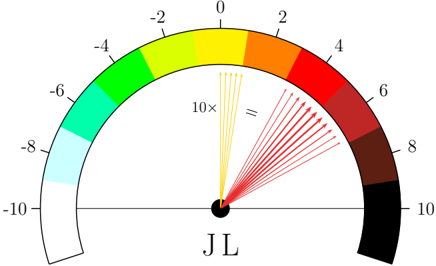
The image depicts a semicircular gauge with a color gradient scale ranging from -10 to 10. A central point labeled "JL" emits arrows pointing to specific regions on the scale. The gauge uses a color-coded legend to map values to visual segments, with a legend positioned on the left side.
### Components/Axes
- **Scale**:
- Semicircular arc divided into 11 segments, labeled with integers from -10 (bottom-left) to 10 (bottom-right).
- Color gradient transitions from white (-10) to black (10), passing through light blue, green, yellow, orange, red, and dark red.
- **Legend**:
- Vertical color bar on the left, aligned with the scale. Each color block is labeled with its corresponding value (e.g., "-10" for white, "10" for black).
- **Central Point**:
- Labeled "JL" at the center of the semicircle.
- **Arrows**:
- Multiple arrows emanate from "JL," pointing to regions on the scale. Arrows are colored yellow, orange, and red, matching the legend.
### Detailed Analysis
- **Scale Segments**:
- **-10 to -6**: White to light blue.
- **-6 to -4**: Light blue to green.
- **-4 to -2**: Green to yellow.
- **-2 to 0**: Yellow to orange.
- **0 to 2**: Orange to red.
- **2 to 4**: Red to dark red.
- **4 to 10**: Dark red to black.
- **Arrows**:
- Yellow arrows point to the **-2 to 0** (yellow/orange) region.
- Orange arrows point to the **0 to 2** (orange/red) region.
- Red arrows point to the **2 to 4** (red/dark red) region.
- **Legend Placement**:
- The legend is vertically aligned on the left, with color blocks matching the scale’s gradient.
### Key Observations
1. The gauge measures a variable (possibly force, pressure, or directional magnitude) with a range of -10 to 10.
2. Arrows from "JL" indicate measurements in the **positive range** (0 to 4), with higher values (2–4) emphasized by red arrows.
3. The color gradient provides a visual cue for magnitude, with darker colors representing higher absolute values.
4. The semicircular design suggests a directional or rotational component, though no explicit angular markers are present.
### Interpretation
- The gauge likely represents a system where "JL" is a reference point (e.g., a joint, load, or sensor) measuring a variable that can be positive or negative.
- The arrows’ placement and color suggest the current measurement is in the **2–4 range**, with red arrows indicating higher intensity.
- The legend’s alignment with the scale ensures clarity, but the lack of explicit units (e.g., Newtons, degrees) limits quantitative interpretation.
- The semicircular format may imply a bidirectional or cyclical measurement, though this is speculative without additional context.
## Notes
- No textual data beyond labels and legend is present.
- The diagram prioritizes visual representation over numerical precision, relying on color and positioning for interpretation.
- The relationship between "JL" and the scale suggests a causal or correlational link, but the exact nature of "JL" remains undefined.