## Diagram: Hardware Data Flow and Synchronization Workflow
### Overview
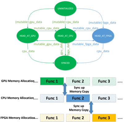
The diagram illustrates a multi-stage data flow and synchronization process across GPU, CPU, and FPGA memory systems. It uses color-coded nodes and arrows to represent data types, hardware components, and synchronization steps.
### Components/Axes
- **Nodes**:
- **UNINITIALIZED** (central node, no color)
- **HEAD_AT_GPU** (green)
- **HEAD_AT_CPU** (blue)
- **HEAD_AT_FPGA** (yellow)
- **SYNCED** (central node, no color)
- **Arrows**:
- Labeled with data types (e.g., `mutable gpu_data`, `Sync up Memory Copy`)
- Colors match memory allocation legends (green=GPU, blue=CPU, yellow=FPGA)
- **Legend**:
- **GPU Memory Allocation**: Green (Func 1, Func 2, Func 3)
- **CPU Memory Allocation**: Blue (Func 1, Func 2, Func 3)
- **FPGA Memory Allocation**: Yellow (Func 1, Func 2, Func 3)
### Detailed Analysis
1. **Data Flow Path**:
- **UNINITIALIZED** → **HEAD_AT_GPU** (via `mutable gpu_data`)
- **HEAD_AT_GPU** → **HEAD_AT_CPU** (via `mutable cpu_data`)
- **HEAD_AT_CPU** → **HEAD_AT_FPGA** (via `mutable fpga_data`)
- **HEAD_AT_FPGA** → **SYNCED** (via `mutable cpu_data`)
- **SYNCED** loops back to **UNINITIALIZED** (via `mutable gpu_data`, `cpu_data`, `fpga_data`)
2. **Function-Level Breakdown**:
- **GPU Memory Allocation**:
- Func 1 → Func 2 (via `Sync up Memory Copy`)
- Func 2 → Func 3 (via `Sync up Memory Copy`)
- **CPU Memory Allocation**:
- Func 1 → Func 2 (via `Sync up Memory Copy`)
- Func 2 → Func 3 (via `Sync up Memory Copy`)
- **FPGA Memory Allocation**:
- Func 1 → Func 2 (via `Sync up Memory Copy`)
- Func 2 → Func 3 (via `Sync up Memory Copy`)
3. **Synchronization Logic**:
- Arrows labeled `Sync up Memory Copy` indicate forced synchronization between functions.
- `mutable` labels suggest data is shared or modified across hardware boundaries.
### Key Observations
- **Cyclic Dependency**: The `SYNCED` node feeds back into `UNINITIALIZED`, implying a loop for iterative processing.
- **Hardware-Specific Data**: Each hardware component (GPU, CPU, FPGA) has distinct data types (`gpu_data`, `cpu_data`, `fpga_data`).
- **Functional Hierarchy**: Functions are organized by memory allocation, with synchronization steps between them.
### Interpretation
This diagram models a distributed computing workflow where data is processed sequentially across GPU, CPU, and FPGA, with synchronization ensuring consistency. The cyclic flow suggests iterative optimization or real-time processing. The use of `mutable` data implies shared ownership, which could introduce concurrency challenges. The color-coded functions highlight hardware-specific memory management, critical for performance tuning in heterogeneous systems.
**Note**: No numerical values or quantitative data are present; the diagram focuses on structural and procedural relationships.