\n
## Diagram: Environment Representation
### Overview
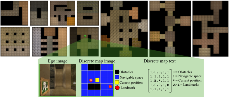
The image presents a comparison of different representations of an indoor environment, likely for a robotic navigation or AI agent. It shows a series of "first-person" views (Ego image), discretized map representations (Discrete map image), and a textual representation of the map (Discrete map text). The goal appears to be illustrating how a continuous visual environment can be abstracted into discrete, symbolic representations.
### Components/Axes
The image is divided into three main sections:
1. **Ego Image:** A 2x6 grid of first-person perspective images of the environment. These images show what an agent "sees" from its current location.
2. **Discrete Map Image:** A 2x2 grid showing a top-down, discretized representation of the environment. This uses a grid-based map where each cell represents a specific state (obstacle, navigable space, agent position, landmark).
3. **Discrete Map Text:** A section containing a sample "Ego image", a 4x4 grid representing the discretized map, and a legend explaining the color coding.
The legend defines the following:
* Blue: Obstacles (value 0)
* White: Navigable space (value 1)
* Yellow: Current position (value B, asterisk *)
* Red: Landmark (value E, A-Z)
### Detailed Analysis or Content Details
**Ego Image:**
The Ego images show a corridor-like environment with textured walls and floors. The perspective changes across the images, suggesting the agent is moving through the environment. The lighting and textures vary, indicating different areas within the space. It's difficult to extract precise details from these images without further processing.
**Discrete Map Image:**
The Discrete Map Image shows a simplified, top-down view of the environment. The grid cells are colored according to the legend. The images show varying arrangements of obstacles and navigable space.
**Discrete Map Text:**
The Discrete Map Text section provides a concrete example of the discretized map. The 4x4 grid has the following configuration (reading row by row, left to right):
```
[1, 0, 0, 1]
[1, 1, 1, 1]
[1, B, *, 1]
[1, 1, 1, 1]
```
Where:
* 1 represents Navigable space
* 0 represents Obstacles
* B represents Current position
* \* represents Current position (duplicate of B)
* E represents Landmarks (not present in this example)
The legend also provides a matrix representation of the color coding:
```
[ 1, 0, 0, 1 ] = Obstacles
[ 1, 1, 1, 1 ] = Navigable space
[ 1, B, *, 1 ] = Current position
[ 1, 1, 1, 1 ] = Landmarks
```
### Key Observations
* The discretization process simplifies the environment, losing fine-grained details present in the Ego images.
* The current position is represented by both 'B' and '*' in the example map, which is redundant.
* The Discrete Map Image and Discrete Map Text sections provide consistent representations of the environment.
* The Ego images provide a visual context for understanding the abstracted representations.
### Interpretation
This diagram illustrates a common approach in robotics and AI: representing a continuous environment in a discrete form for planning and decision-making. The Ego images represent the raw sensory input, while the Discrete Map Image and Text represent the processed, symbolic representation. This abstraction allows algorithms to reason about the environment without dealing with the complexity of raw pixel data. The discretization process involves identifying obstacles, navigable spaces, and key locations (landmarks). The choice of discretization resolution (grid size) impacts the accuracy and computational cost of planning algorithms. The redundancy in representing the current position ('B' and '\*') suggests a potential area for optimization in the representation. The diagram highlights the trade-off between realism (Ego images) and computational efficiency (Discrete maps).