TECHNICAL ASSET FINGERPRINT
9ffedbf21bbd14b9a01ecaa3
Click to view fullscreen
Press ESC or click to close
FOUND IN PAPERS
EXPERT: healer-alpha-free VERSION 1
RUNTIME: free/openrouter/healer-alpha
INTEL_VERIFIED
## Diagram: Environment Representation for Navigation
### Overview
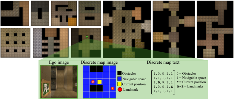
The image is a composite diagram illustrating how a 3D environment is represented in different formats for an autonomous agent or navigation system. It consists of two main sections: a top section showing eight different top-down map layouts, and a bottom section explaining the relationship between a first-person view, a grid-based map, and a textual representation of that map.
### Components/Axes
The image is segmented into distinct regions:
1. **Top Section (Map Layouts):** Contains eight small, square images arranged in two rows of four. Each shows a top-down, pixelated view of an environment with different patterns of brown/tan (navigable space) and black (obstacles) tiles. One image in the top row includes an orange tile. One image in the bottom row includes a green marker.
2. **Bottom Section (Explanation):** Contains three labeled components and a legend, arranged horizontally.
* **Left: "Ego image"** - A first-person perspective view from within a 3D environment, showing a room with a painting on the wall.
* **Center: "Discrete map image"** - A 7x7 grid (blue background) with colored squares representing the environment state.
* **Right: "Discrete map text"** - A textual, matrix-style representation of the grid.
* **Legend:** Positioned between the "Discrete map image" and "Discrete map text," defining the color and symbol codes.
### Detailed Analysis
**Top Section - Map Layouts:**
* The eight maps show varied configurations of obstacles and open space. They appear to be different training or test environments.
* **Top Row, Left to Right:**
1. A map with a large black obstacle in the top-left.
2. A map with a central black obstacle.
3. A map with a complex obstacle pattern and one orange tile (possibly a special landmark or goal).
4. A map with two horizontal black obstacle bars.
* **Bottom Row, Left to Right:**
1. A map with a grid of small black obstacles.
2. A map with vertical black obstacle stripes.
3. A map with a green marker (likely the agent's starting position) on a grassy area, with a black obstacle to the left.
4. A map with a cross-shaped navigable area surrounded by obstacles.
**Bottom Section - Representation Explanation:**
* **Ego image:** Shows a textured 3D scene. A painting of a person is visible on the left wall. The floor and walls are a uniform brown.
* **Discrete map image (Grid):** A 7x7 grid.
* **Background:** Blue squares represent "Navigable space."
* **Black squares:** Represent "Obstacles." They form a pattern matching the layout in one of the top maps (specifically, the third map in the top row).
* **Yellow square:** Represents the "Current position" of the agent. It is located at grid coordinates (row 4, column 4) if counting from the top-left as (1,1).
* **Red circle:** Represents a "Landmark." It is located at grid coordinates (row 6, column 6).
* **Discrete map text (Matrix):** A 7x7 matrix of characters corresponding directly to the grid.
```
[1, 0, 0, 1, 1, 1, 1]
[1, 1, 1, 1, 1, 1, 1]
[1, B, *, 1, E, 1, 1]
[1, 0, 0, 1, 1, 1, 1]
[1, 1, 1, 1, 1, 1, 1]
```
* **Legend Key (Transcribed):**
* `0 = Obstacles`
* `1 = Navigable space`
* `* = Current position`
* `A-Z = Landmarks`
* **Matrix Key Application:**
* `0` and `1` correspond to black and blue squares, respectively.
* The asterisk `*` at position (3,3) corresponds to the yellow "Current position" square.
* The letter `B` at position (3,2) and the letter `E` at position (3,5) are landmarks. In the "Discrete map image," these correspond to the locations of two black squares that are part of the obstacle pattern. This suggests that specific obstacles can also be designated as named landmarks (`B` and `E`).
* The red circle landmark from the grid image is not explicitly marked with a letter in this specific text matrix example, indicating the text representation may show a slightly different state or that the red circle is a generic landmark type not assigned a letter here.
### Key Observations
1. **Multi-Modal Representation:** The core concept is the translation of a continuous 3D world ("Ego image") into a discrete, symbolic grid ("Discrete map image" and "Discrete map text") for computational processing.
2. **Symbolic Encoding:** The system uses a compact encoding scheme: binary values (`0`/`1`) for space type, a special character (`*`) for the agent, and alphabetic characters (`A-Z`) for unique landmarks.
3. **Landmark Ambiguity:** There is a discrepancy between the visual grid (which shows a red circle landmark) and the text matrix (which shows letters `B` and `E` on obstacle tiles). This implies the diagram is illustrating two different landmark designation methods: one visual/iconic (red circle) and one symbolic/alphabetic.
4. **Spatial Consistency:** The pattern of black `0`s in the text matrix perfectly matches the pattern of black squares in the grid image, confirming accurate cross-referencing.
### Interpretation
This diagram is a technical schematic for an **embodied AI or robotics navigation system**. It demonstrates the pipeline from sensory input (first-person view) to an internal, structured world model (the discrete map).
* **What it demonstrates:** The system abstracts the complex visual world into a simplified, grid-based state representation. This abstraction is crucial for path-planning algorithms, reinforcement learning, and symbolic reasoning about space. The "Discrete map text" format is likely the actual input fed into a machine learning model or planning algorithm.
* **Relationship between elements:** The "Ego image" is the raw observation. The "Discrete map image" is a human-interpretable visualization of the agent's internal belief state. The "Discrete map text" is the machine-readable data structure. The top eight maps represent the variety of environments this system is designed to handle.
* **Notable insight:** The use of letters (`A-Z`) for landmarks within obstacle fields is particularly interesting. It suggests the system can identify and label specific, functionally important points within impassable terrain (e.g., "Landmark B is the north-west corner of the central pillar"). This enables more sophisticated navigation commands like "move to a position adjacent to landmark E."
* **Purpose:** The image serves to document and explain the environment encoding scheme used in a research project, likely for a paper or technical report on autonomous navigation, spatial reasoning, or sim-to-real transfer in AI.
DECODING INTELLIGENCE...