## Mixed Diagram: GPU-REASON Pipeline and Intra-REASON Execution
### Overview
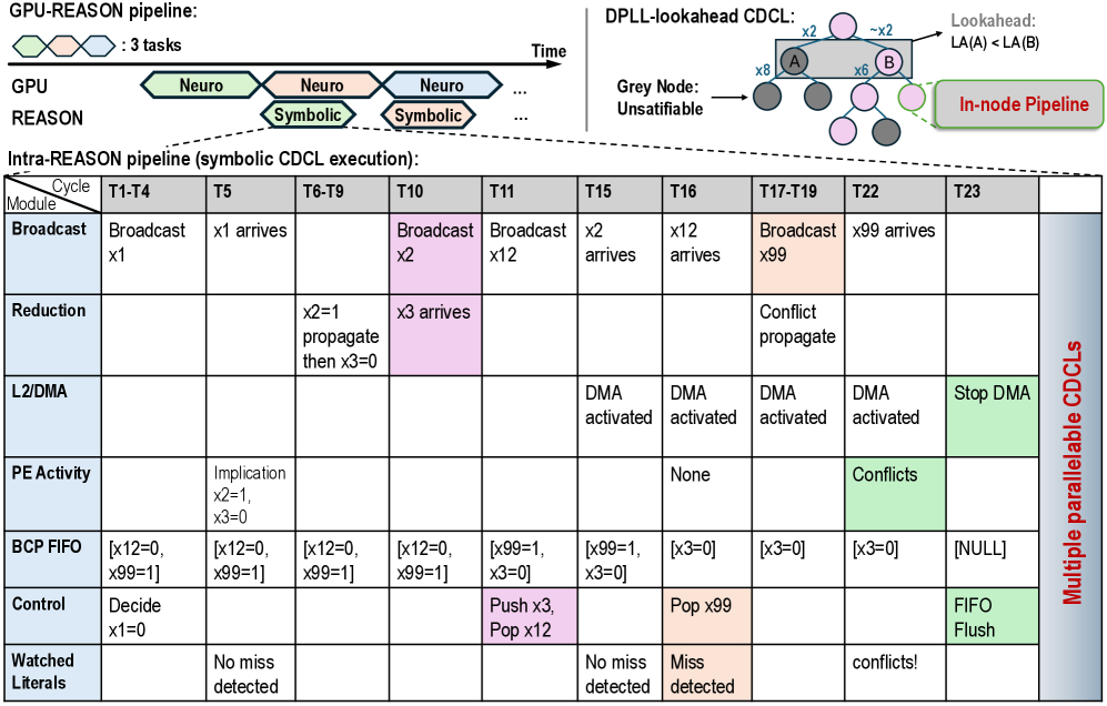
This image illustrates a hybrid computing architecture designed for symbolic CDCL (Conflict-Driven Clause Learning) execution. It is composed of three distinct sections:
1. **Top-Left:** A timeline diagram showing the concurrent execution of "Neuro" (GPU) and "Symbolic" (REASON) tasks.
2. **Top-Right:** A tree diagram representing the DPLL-lookahead CDCL process, highlighting node exploration and "In-node Pipeline" capabilities.
3. **Bottom:** A detailed execution table ("Intra-REASON pipeline") mapping specific module operations across time cycles (T1–T23).
---
### Components/Axes
#### 1. GPU-REASON Pipeline (Top-Left)
* **Legend:** Three overlapping hexagons (Green, Pink, Blue) labeled ": 3 tasks".
* **Axes:** Horizontal axis represents "Time".
* **Rows:**
* **GPU:** Shows "Neuro" tasks (Green, Pink, Green) occurring in a staggered, overlapping fashion.
* **REASON:** Shows "Symbolic" tasks (Pink, Pink) occurring in the gaps between GPU tasks.
#### 2. DPLL-lookahead CDCL (Top-Right)
* **Structure:** A tree diagram with nodes labeled "A" and "B".
* **Annotations:**
* "Lookahead: LA(A) < LA(B)" pointing to the branch between A and B.
* "Grey Node: Unsatisfiable" pointing to dark grey circles.
* "In-node Pipeline" pointing to a dashed bubble enclosing a light pink node.
#### 3. Intra-REASON Pipeline (Bottom Table)
* **Structure:** A matrix where rows represent functional modules and columns represent time cycles.
* **Modules (Rows):** Broadcast, Reduction, L2/DMA, PE Activity, BCP FIFO, Control, Watched Literals.
* **Time Cycles (Columns):** T1-T4, T5, T6-T9, T10, T11, T15, T16, T17-T19, T22, T23.
* **Right-side Label:** "Multiple parallelable CDCLs" (vertical text).
---
### Content Details: Intra-REASON Pipeline Table
| Module | T1-T4 | T5 | T6-T9 | T10 | T11 | T15 | T16 | T17-T19 | T22 | T23 |
| :--- | :--- | :--- | :--- | :--- | :--- | :--- | :--- | :--- | :--- | :--- |
| **Broadcast** | Broadcast x1 | x1 arrives | | Broadcast x2 (Pink) | Broadcast x12 | x2 arrives | x12 arrives | Broadcast x99 (Orange) | x99 arrives | |
| **Reduction** | | | x2=1 propagate then x3=0 | x3 arrives (Pink) | | | | Conflict propagate | | |
| **L2/DMA** | | | | | | DMA activated | DMA activated | DMA activated | DMA activated | Stop DMA (Green) |
| **PE Activity** | | Implication x2=1, x3=0 | | | | | None | | Conflicts (Green) | |
| **BCP FIFO** | [x12=0, x99=1] | [x12=0, x99=1] | [x12=0, x99=1] | [x12=0, x99=1] | [x99=1, x3=0] | [x99=1, x3=0] | [x3=0] | [x3=0] | [x3=0] | [NULL] |
| **Control** | Decide x1=0 | | | | Push x3, Pop x12 (Pink) | | Pop x99 (Orange) | | | FIFO Flush (Green) |
| **Watched Literals** | | No miss detected | | | | No miss detected | Miss detected (Orange) | | conflicts! | |
---
### Key Observations
* **Color Coding:**
* **Pink:** Indicates active control/broadcast operations (e.g., T10 Broadcast x2, T11 Push/Pop).
* **Orange:** Indicates conflict/miss events (e.g., T16 Miss detected, T17-T19 Broadcast x99).
* **Green:** Indicates termination or conflict states (e.g., T22 Conflicts, T23 Stop DMA/FIFO Flush).
* **Data Flow:** The BCP FIFO (Boolean Constraint Propagation First-In-First-Out) buffer maintains state across cycles, with values like `x99=1` and `x3=0` persisting until they are popped or updated.
* **Parallelism:** The "Multiple parallelable CDCLs" label on the right suggests that the table represents a single slice of a larger, parallelized execution architecture.
* **Temporal Gaps:** There are gaps in the timeline (e.g., between T11 and T15, T19 and T22) suggesting asynchronous processing or idle cycles where no specific module activity is recorded.
---
### Interpretation
This diagram describes a hardware-accelerated solver architecture. The **GPU-REASON pipeline** (top-left) demonstrates a heterogeneous computing model where the GPU handles "Neuro" (likely neural network-based heuristics or predictions) and the REASON unit handles "Symbolic" (logical deduction/CDCL) tasks.
The **Intra-REASON pipeline** table provides a low-level trace of the symbolic solver's state machine.
* **The Logic:** The solver is performing clause learning. It broadcasts literals (x1, x2, x12, x99), propagates implications (x2=1, x3=0), and manages a FIFO queue of literals.
* **Conflict Handling:** The system is designed to detect "Misses" (Watched Literals) and "Conflicts" (PE Activity). When a conflict occurs (T17-T19, T22), the system triggers a propagation and eventually flushes the FIFO (T23), indicating a reset or backtracking step common in CDCL algorithms.
* **Efficiency:** The "In-node Pipeline" (top-right) and the table suggest that the architecture is optimized to perform these logical operations in hardware, allowing for "Lookahead" capabilities where the system can evaluate branches (A vs B) before fully committing to them, thereby pruning the search space more efficiently than a standard CPU-based solver.