## Diagram: Recursive Logical Formula with Geometric Representation
### Overview
The image displays a technical diagram illustrating a recursive logical or mathematical process. It consists of three vertically aligned rows, each pairing a symbolic label on the left with a complex logical expression and a corresponding blue geometric shape on the right. The diagram appears to depict a stepwise construction or transformation, likely from a field such as mathematical logic, set theory, or theoretical computer science.
### Components/Axes
The diagram is organized into three distinct rows, each with two primary components:
1. **Left Column (Labels):**
* **Top Row:** The label is the lowercase letter **`n`**.
* **Middle Row:** The label is the Greek lowercase letter sigma **`σ`**.
* **Bottom Row:** The label is the equation **`y = ⌈σ⌉`**. The symbol `⌈ ⌉` typically denotes the ceiling function.
2. **Right Column (Expressions & Shapes):**
* Each row contains a logical expression written in a formal notation using symbols like `∃` (there exists), `∧` (logical AND), and a function or predicate named `φ_DIAG`.
* Below each expression is a light blue geometric shape with a black outline.
* **Top Shape:** An inverted (downward-pointing) isosceles triangle.
* **Middle Shape:** Two parallelograms, slanted and positioned side-by-side, forming a broken or split shape.
* **Bottom Shape:** A single, wider parallelogram.
### Detailed Analysis
The logical expressions show a clear recursive pattern, building upon the expression from the row above.
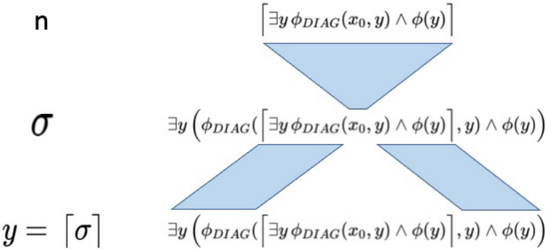
* **Row 1 (Label: `n`):**
* **Expression:** `[∃y φ_DIAG(x₀, y) ∧ φ(y)]`
* **Shape:** A single inverted triangle.
* **Interpretation:** This appears to be the base case or initial formula. It asserts the existence of a `y` such that a diagonal predicate `φ_DIAG` holds for `(x₀, y)` and some property `φ(y)` also holds.
* **Row 2 (Label: `σ`):**
* **Expression:** `∃y (φ_DIAG([∃y φ_DIAG(x₀, y) ∧ φ(y)], y) ∧ φ(y))`
* **Shape:** Two adjacent parallelograms.
* **Interpretation:** This is the first recursive step. The entire expression from Row 1 (enclosed in square brackets `[...]`) is now used as the first argument to the `φ_DIAG` function. The structure is: `∃y (φ_DIAG( [Row 1 Expression], y) ∧ φ(y))`.
* **Row 3 (Label: `y = ⌈σ⌉`):**
* **Expression:** `∃y (φ_DIAG([∃y (φ_DIAG([∃y φ_DIAG(x₀, y) ∧ φ(y)], y) ∧ φ(y))], y) ∧ φ(y))`
* **Shape:** A single, wider parallelogram.
* **Interpretation:** This is the second recursive step. The entire expression from Row 2 is now nested as the first argument within a new `φ_DIAG` call. The pattern continues: `∃y (φ_DIAG( [Row 2 Expression], y) ∧ φ(y))`.
**Spatial Grounding:** The labels (`n`, `σ`, `y = ⌈σ⌉`) are vertically aligned on the far left. The corresponding expressions and shapes are centered horizontally to the right of their labels. The shapes are positioned directly beneath their associated expressions.
### Key Observations
1. **Recursive Nesting:** The core observation is the deep, recursive nesting of the logical formula. Each step encapsulates the entire previous formula within the `φ_DIAG` function.
2. **Geometric Metaphor:** The shapes visually metaphorize the process:
* The initial **triangle** might represent a foundational or singular starting point.
* The **split parallelograms** in the second step could symbolize a branching, duplication, or application of the base formula.
* The final, **wider parallelogram** may represent the consolidated or expanded result of the second recursion.
3. **Label Progression:** The left-hand labels (`n`, `σ`, `y = ⌈σ⌉`) suggest a progression from an integer or index (`n`), to a function or mapping (`σ`), to a specific value `y` defined as the ceiling of `σ`.
### Interpretation
This diagram is a formal representation of a **diagonalization argument** or a **self-referential construction**, common in mathematical logic and the foundations of computation (e.g., proofs related to the Halting Problem or Gödel's incompleteness theorems).
* **What it demonstrates:** It visually outlines the step-by-step construction of a complex logical statement that likely aims to create a contradiction or prove a limitation. The `φ_DIAG` function is central, suggesting it performs a "diagonal" operation—perhaps constructing an object that differs from every object in a given list.
* **Relationship between elements:** The left labels define the "stage" or "name" of the construction. The right side shows the actual formula at that stage, with the geometric shape providing an abstract visual cue for the formula's structure or the operation being performed. The recursion is the engine of the construction.
* **Notable Anomaly/Pattern:** The most striking pattern is the exponential growth in formula complexity with each step, while the visual shape simplifies from a triangle to a split form to a unified form. This could imply that the logical complexity increases even as the conceptual "output" or "result" of the operation becomes more consolidated. The use of the ceiling function `⌈σ⌉` in the final label hints that `σ` might be a function or set, and `y` is a specific integer derived from it, which is then used in the final, most nested expression.
**In essence, the diagram is a blueprint for building a highly self-referential logical sentence, using recursion and diagonalization as its core mechanisms.**