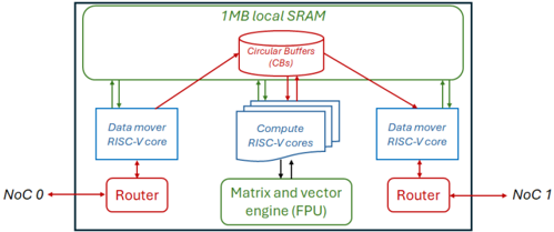
## Block Diagram: Processor Architecture
### Overview
The image is a block diagram illustrating the architecture of a processor. It shows the interconnection of various components such as data movers, compute cores, circular buffers, routers, and a matrix/vector engine. The diagram highlights the flow of data between these components.
### Components/Axes
* **1MB local SRAM:** Located at the top of the diagram, enclosed in a green box.
* **Circular Buffers (CBs):** A red oval shape at the top-center, connected to the SRAM and compute cores.
* **Data mover RISC-V core:** Two blue rectangular boxes, one on the left and one on the right.
* **Compute RISC-V cores:** A stack of blue rectangular boxes in the center.
* **Matrix and vector engine (FPU):** A green rectangular box at the bottom-center.
* **Router:** Two red rectangular boxes, one on the left and one on the right.
* **NoC 0:** Label on the left side, connected to the left Router.
* **NoC 1:** Label on the right side, connected to the right Router.
* **Connections:** Green arrows indicate data flow between the SRAM and the Data movers. Red arrows indicate data flow between the Circular Buffers and the Data movers. Black arrows indicate data flow between the Data movers and the Routers, and between the Compute cores and the Matrix and vector engine.
### Detailed Analysis
* **SRAM and Circular Buffers:** The 1MB local SRAM is connected to the Circular Buffers (CBs).
* **Data Movers:** Two Data mover RISC-V cores are present, one on each side of the Compute RISC-V cores.
* **Compute Cores:** The Compute RISC-V cores are connected to the Circular Buffers and the Matrix and vector engine.
* **Routers:** The Routers are connected to the Data movers and the NoC (Network on Chip).
* **Data Flow:** Data flows from the SRAM to the Circular Buffers, then to the Data movers and Compute cores. The Matrix and vector engine processes data from the Compute cores. The Routers facilitate communication with the NoC.
### Key Observations
* The architecture appears to be designed for parallel processing, with multiple compute cores and data movers.
* The Circular Buffers likely serve as a temporary storage area for data being processed.
* The Matrix and vector engine suggests that the processor is optimized for linear algebra operations.
* The NoC connections indicate that this processor can be integrated into a larger system.
### Interpretation
The diagram illustrates a processor architecture designed for high-performance computing, likely in applications involving signal processing, machine learning, or scientific simulations. The presence of multiple compute cores, data movers, and a matrix/vector engine suggests a focus on parallel processing and efficient handling of large datasets. The Circular Buffers likely play a role in optimizing data access and reducing memory latency. The NoC connections enable the processor to communicate with other components in a system-on-chip (SoC) environment.