\n
## Diagram: System Architecture Block Diagram
### Overview
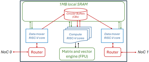
The image presents a block diagram illustrating the architecture of a system, likely a processing unit or accelerator. The diagram depicts the interconnection of various components including routers, RISC-V cores, a matrix/vector engine, circular buffers, and local SRAM. The overall structure suggests a dataflow-oriented architecture with dedicated components for data movement, computation, and storage.
### Components/Axes
The diagram contains the following components and labels:
* **1MB local SRAM:** A large block at the top, representing the local static random-access memory.
* **Circular Buffers (CBs):** Located within the 1MB local SRAM, depicted as a circular shape.
* **Data mover RISC-V-core:** Two blocks labeled "Data mover RISC-V-core" positioned on the left and right sides.
* **Compute RISC-V-cores:** A block labeled "Compute RISC-V-cores" containing multiple smaller rectangular blocks, representing multiple cores.
* **Matrix and vector engine (FPU):** A block labeled "Matrix and vector engine (FPU)" positioned in the center-bottom.
* **Router:** Two blocks labeled "Router" positioned on the left and right sides, connected to "NoC 0" and "NoC 1" respectively.
* **NoC 0:** Label indicating an input/output connection on the left side.
* **NoC 1:** Label indicating an input/output connection on the right side.
* **Arrows:** Red and green arrows indicating data flow between components.
### Detailed Analysis or Content Details
The diagram shows a system with the following connections:
* **NoC 0** connects to a **Router** on the left.
* The left **Router** connects to the **Data mover RISC-V-core** on the left, and to the **Circular Buffers (CBs)** via a red arrow.
* **NoC 1** connects to a **Router** on the right.
* The right **Router** connects to the **Data mover RISC-V-core** on the right, and to the **Circular Buffers (CBs)** via a red arrow.
* The **Circular Buffers (CBs)** connect to both **Data mover RISC-V-cores** and the **Compute RISC-V-cores** via green arrows.
* The **Compute RISC-V-cores** connect to the **Matrix and vector engine (FPU)** via green arrows.
* The **Data mover RISC-V-cores** connect to the **Matrix and vector engine (FPU)** via red arrows.
* The **1MB local SRAM** encompasses the **Circular Buffers (CBs)**.
The arrows indicate the direction of data flow. Red arrows likely represent control or address signals, while green arrows represent data transfer.
### Key Observations
The architecture appears to be designed for efficient data processing, with dedicated cores for data movement and computation. The use of circular buffers suggests a streaming data processing approach. The matrix and vector engine (FPU) indicates a focus on numerical computations. The NoC connections suggest integration with a larger system.
### Interpretation
This diagram illustrates a heterogeneous computing architecture. The separation of data movement (Data mover RISC-V-cores) and computation (Compute RISC-V-cores and FPU) allows for parallel processing and optimized data flow. The local SRAM provides fast access to data, while the circular buffers enable efficient handling of streaming data. The NoC connections suggest that this unit is part of a larger network-on-chip system. The architecture is likely designed for applications requiring high throughput and low latency, such as signal processing, machine learning, or image processing. The use of RISC-V cores suggests a focus on open-source and customizable hardware. The FPU indicates a specialization for matrix and vector operations, common in many modern computational tasks.