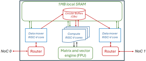
## Block Diagram: System Architecture with RISC-V Cores and Network-on-Chip (NoC)
### Overview
The diagram illustrates a system architecture featuring RISC-V cores, a matrix/vector engine (FPU), circular buffers, and Network-on-Chip (NoC) communication. It highlights data flow between components, including routers, data movers, and compute units, with a 1MB local SRAM at the top.
---
### Components/Axes
- **Top Section**:
- **1MB local SRAM** (green rectangle)
- **Circular Buffers (CBs)** (red cylinder)
- **Middle Section**:
- **Data mover RISC-V core** (blue rectangle, left)
- **Compute RISC-V cores** (blue rectangles, center)
- **Matrix and vector engine (FPU)** (green rectangle, center)
- **Data mover RISC-V core** (blue rectangle, right)
- **Bottom Section**:
- **Router** (red rectangle, left)
- **Router** (red rectangle, right)
- **NoC Labels**:
- **NoC 0** (left router)
- **NoC 1** (right router)
- **Arrows**:
- Red arrows indicate data flow between routers and NoC.
- Green arrows indicate data flow between SRAM, CBs, and compute units.
---
### Detailed Analysis
1. **1MB local SRAM**:
- Positioned at the top, connected via green arrows to circular buffers (CBs).
- Likely serves as a high-speed memory buffer for the system.
2. **Circular Buffers (CBs)**:
- Centralized red cylinder connected to both data movers and compute cores.
- Acts as a staging area for data between SRAM and processing units.
3. **Data Mover RISC-V Cores**:
- Two instances (left and right) labeled "Data mover RISC-V core."
- Connected to CBs via green arrows and to routers via red arrows.
- Likely handle data transfer between memory and compute units.
4. **Compute RISC-V Cores**:
- Stacked blue rectangles in the center, connected to CBs and FPU.
- Process data before passing it to the FPU.
5. **Matrix and Vector Engine (FPU)**:
- Green rectangle at the center, connected to compute cores.
- Specialized for matrix/vector operations, critical for AI/ML workloads.
6. **Routers**:
- Two red rectangles (left and right) labeled "Router."
- Connected to NoC 0 and NoC 1 via red arrows.
- Manage packet switching for NoC communication.
7. **Network-on-Chip (NoC)**:
- Labeled "NoC 0" and "NoC 1" at the bottom edges.
- Red arrows indicate bidirectional communication between routers and NoC.
---
### Key Observations
- **Data Flow**:
- Data moves from 1MB SRAM → CBs → Compute cores → FPU → Routers → NoC.
- Red arrows (NoC) and green arrows (SRAM/CBs) suggest prioritized pathways for different data types.
- **Symmetry**:
- Left and right sides mirror each other, with identical data mover cores and routers.
- **Color Coding**:
- Red: Routers and NoC (high-speed communication).
- Blue: RISC-V cores (processing units).
- Green: SRAM and FPU (memory and specialized compute).
---
### Interpretation
This architecture is optimized for **high-throughput, low-latency computing**, likely for AI/ML or HPC applications. The use of RISC-V cores suggests customizability and energy efficiency. The 1MB SRAM and circular buffers indicate a focus on minimizing memory bottlenecks, while the FPU offloads matrix operations. The NoC (NoC 0/1) enables on-chip communication, reducing reliance on external buses. The symmetric design implies scalability, with potential for additional compute units or routers in larger systems.
**Notable Trends**:
- Centralization of compute and memory resources around the FPU and CBs.
- Redundant data movers suggest fault tolerance or load balancing.
- NoC integration highlights a move toward heterogeneous, tightly coupled systems.