\n
## Diagram: Digital Logic Circuit - Adder with Carry
### Overview
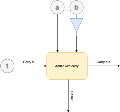
The image is a technical diagram illustrating a digital logic circuit component, specifically an "Adder with carry" block. It shows the inputs, internal processing block, and outputs of a circuit that performs binary addition with a carry input. The diagram uses standard symbols for logic gates and functional blocks.
### Components/Axes
The diagram consists of the following labeled components and connections, arranged in a flow from top/left to bottom/right:
1. **Input Nodes (Top):**
* A circle labeled **"a"** (top-left).
* A circle labeled **"b"** (top-right).
2. **Logic Gate (Top-Right):**
* A light blue triangle with a circle at its output, representing a **NOT gate (inverter)**. It is connected to the "b" input.
3. **Input Node (Left):**
* A circle labeled **"1"** (center-left).
4. **Central Processing Block:**
* A large, light yellow rectangle with rounded corners labeled **"Adder with carry"** in its center.
5. **Connections and Signal Labels:**
* A line from the "a" circle goes directly down into the top of the "Adder with carry" block.
* A line from the "b" circle goes through the NOT gate and then down into the top of the "Adder with carry" block.
* A line from the "1" circle goes horizontally to the right, labeled **"Carry in"**, and enters the left side of the "Adder with carry" block.
* A line exits the right side of the "Adder with carry" block, labeled **"Carry out"**, and points to the right.
* A line exits the bottom of the "Adder with carry" block, labeled **"Result"**, and points downward.
### Detailed Analysis
* **Signal Flow:** The primary flow is from the top (inputs `a` and `b`) and left (Carry in `1`) into the central adder block. The processed signals then flow out to the right (Carry out) and bottom (Result).
* **Input Processing:** Input `b` is inverted by the NOT gate before entering the adder. Input `a` and the Carry in signal enter directly.
* **Central Block:** The "Adder with carry" block is the core functional unit. It is a black box in this diagram; its internal logic (e.g., full adder circuitry using XOR, AND, OR gates) is not shown.
* **Outputs:** The block produces two outputs: a "Result" (the sum bit) and a "Carry out" (the carry bit for the next stage).
### Key Observations
1. **Specific Input Value:** The Carry in input is explicitly set to the logic value **"1"**.
2. **Inverted Input:** The `b` input is passed through an inverter, meaning the adder receives `NOT b` instead of `b`.
3. **Abstraction:** The diagram abstracts the internal complexity of the adder, focusing on its interface and role within a larger system.
4. **Spatial Layout:** Inputs are positioned at the top and left, outputs at the right and bottom, following a conventional left-to-right, top-to-bottom signal flow.
### Interpretation
This diagram represents a specific configuration of a binary adder circuit, likely a **full adder**, which adds three bits: `a`, `b`, and a carry-in (`Cin`). The notable configuration here is that the `b` input is inverted.
* **Function:** The circuit computes `Result = a + (NOT b) + 1` (where `+` denotes binary addition). The `Carry out` is the overflow from this addition.
* **Purpose of Inversion:** Inverting the `b` input and setting Carry in to `1` is a standard technique used in digital circuits to perform **subtraction** using two's complement logic. This specific setup calculates `a - b` (assuming `a` and `b` are single bits and the result is represented by the `Result` and `Carry out` bits).
* In two's complement, `-b` is equivalent to `(NOT b) + 1`.
* Therefore, this circuit effectively computes `a + (-b) = a - b`.
* **System Context:** This block would be one stage in a multi-bit adder/subtractor unit within a computer's Arithmetic Logic Unit (ALU). The `Carry out` from this stage would connect to the `Carry in` of the next more significant bit stage.
* **Data Flow:** The diagram clearly shows the transformation of the `b` signal and the integration of a constant carry-in to achieve a specific arithmetic operation, moving beyond simple addition.