\n
## Diagram: Transformation of a Flow Network
### Overview
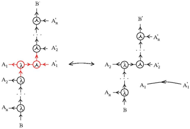
The image depicts a diagram illustrating a transformation of a flow network. Two network configurations are shown, connected by a bidirectional arrow indicating a transformation process. The networks consist of nodes connected by directed edges, with labels indicating the flow variables involved. The diagram appears to represent a mathematical or engineering concept related to network flow or signal processing.
### Components/Axes
The diagram consists of two network structures, labeled with variables A1, A2, An, B, A'1, A'2, A'n, and B'. The nodes are represented by circles, and the flow direction is indicated by arrows. The central node in both networks is highlighted with a red circle. A bidirectional arrow connects the two networks, suggesting a transformation or mapping between them. There are no explicit axes or scales.
### Detailed Analysis or Content Details
**Left Network:**
* The network has a central node where flows A1 and A2 converge, and then split into A'1 and A'2.
* Flow B enters from the bottom and splits into A1, A2, and An.
* Flows A1, A2, and An converge at the central node.
* Flow B' exits from the top.
**Right Network:**
* Flow B enters from the bottom.
* Flows A1 and A2 converge at a central node, splitting into A'1 and A'2.
* Flow A'n exits from the top.
* Flow A1 is transformed into A'1.
* Flow A2 is transformed into A'2.
**Transformation:**
* The bidirectional arrow indicates a transformation between the two networks.
* The transformation appears to involve a change in the flow paths and variable assignments.
### Key Observations
* The central node in both networks is highlighted, suggesting its importance in the transformation.
* The transformation involves a rearrangement of flow paths and variable assignments.
* The diagram does not provide numerical values or specific equations, but rather a conceptual representation of a network transformation.
### Interpretation
The diagram likely represents a transformation of a network flow problem. The left network could represent an initial state, and the right network represents a transformed state. The transformation could be a simplification, a change of variables, or a different representation of the same underlying flow problem. The highlighted central node suggests that this node plays a crucial role in the transformation process. The bidirectional arrow indicates that the transformation may be reversible or have an inverse transformation. The diagram is abstract and requires additional context to fully understand the specific meaning of the transformation. It could be related to concepts in linear algebra, graph theory, or network optimization. The diagram is a visual representation of a mathematical or engineering concept, and its purpose is to illustrate the relationship between the two network configurations. The absence of numerical data suggests that the diagram is intended to convey a general principle rather than a specific solution.