## Diagram: Maze-like Grid with Pathways and Nodes
### Overview
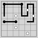
The image depicts a grid-based maze structure composed of interconnected black lines (pathways) and white circular nodes. The grid is divided into 10x10 cells, with pathways forming a non-linear route from the top-left to the bottom-right. White nodes are positioned at specific intersections, while black nodes anchor the start/end points. No explicit legend or labels are present.
### Components/Axes
- **Grid Structure**:
- 10x10 cells with uniform gray fill.
- Black lines represent pathways; thickness is consistent (~2px).
- White nodes (circles, ~0.5cm diameter) are placed at specific grid intersections.
- **Nodes**:
- **Black Nodes**: Two large black nodes (diameter ~1cm) at the top-left and bottom-right corners, likely representing start/end points.
- **White Nodes**: Five smaller white nodes distributed along the pathways.
- **Flow Direction**:
- Pathways originate from the top-left black node, branch into multiple routes, and converge toward the bottom-right black node.
- Dead ends and loops are present (e.g., a loop near the top-right quadrant).
### Detailed Analysis
- **Pathway Distribution**:
- Total pathways: ~25 segments.
- Branching occurs at white nodes (e.g., a node at (3,4) splits into two paths).
- Dead ends: Two segments terminate without connecting to other nodes (e.g., near (7,2)).
- **Node Placement**:
- White nodes are spaced irregularly, with no clear pattern.
- Black nodes are positioned at grid corners (top-left: (0,0); bottom-right: (9,9)).
- **Uncertainty**:
- No numerical labels or scales are visible.
- Pathway lengths cannot be quantified without a reference scale.
### Key Observations
1. **Complexity**: The maze has multiple routes but includes intentional obstacles (dead ends).
2. **Node Function**: White nodes may act as checkpoints or decision points in a pathfinding algorithm.
3. **Symmetry**: No symmetrical design; pathways are asymmetrically distributed.
### Interpretation
This diagram likely represents a **pathfinding problem** or **network topology**. The white nodes could symbolize critical junctions (e.g., servers in a network) or obstacles (e.g., blocked paths). The absence of a legend or labels suggests the diagram is conceptual rather than data-driven. The dead ends and loops imply inefficiencies in the route, which might be analyzed using algorithms like Depth-First Search (DFS) or Breadth-First Search (BFS). The lack of numerical data limits quantitative analysis, but the spatial arrangement emphasizes connectivity and decision-making at nodes.
## Notes
- No textual labels, legends, or axis titles are present.
- The image focuses on spatial relationships rather than numerical data.
- The purpose appears to be illustrative (e.g., teaching maze-solving algorithms or network design).