## Diagram: 2D Layout with 3D Structural Options
### Overview
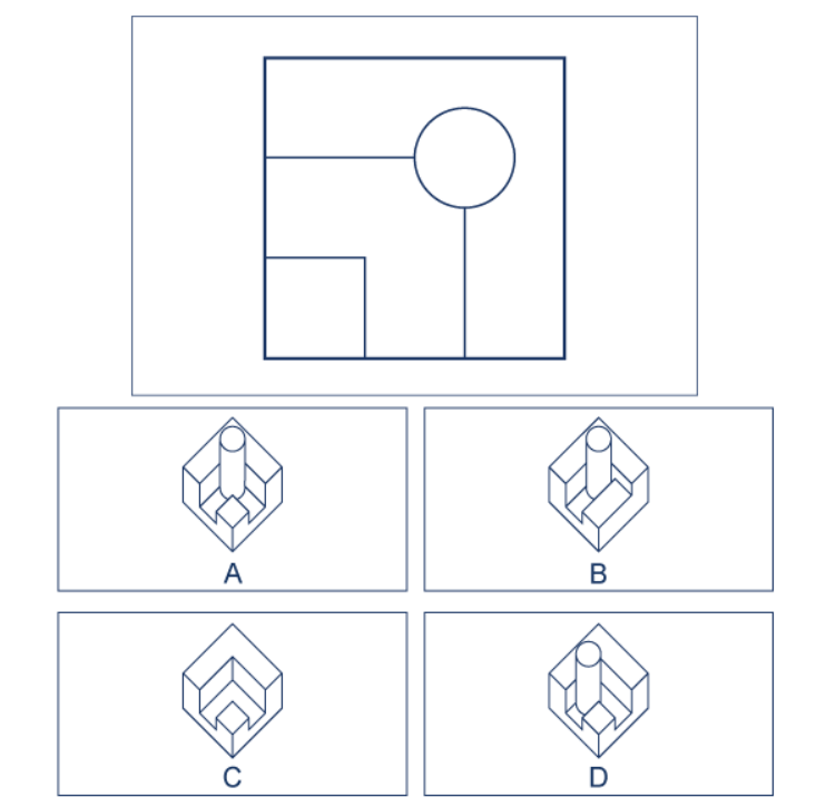
The image presents a technical diagram divided into two sections:
1. **Top Section**: A 2D layout of a square divided into geometric regions with a central circular element and connecting lines.
2. **Bottom Section**: Four 3D structural diagrams labeled **A**, **B**, **C**, and **D**, each depicting variations of a cylindrical object integrated into a rectangular framework.
### Components/Axes
#### Top Section (2D Layout):
- **Square Framework**: A large square divided into three distinct regions:
- **Left Region**: A smaller square (occupies ~1/4 of the square’s width).
- **Middle Region**: A vertical rectangle (occupies ~1/2 of the square’s width).
- **Right Region**: A larger horizontal rectangle (occupies ~1/4 of the square’s width).
- **Central Circle**: A circle positioned at the junction of the middle and right regions.
- **Connecting Lines**:
- A vertical line extends downward from the circle’s center to the bottom edge of the square.
- Two diagonal lines extend from the circle’s center to the top and bottom edges of the right region.
#### Bottom Section (3D Diagrams):
- **Labels**: Four options labeled **A**, **B**, **C**, and **D**.
- **Common Elements**:
- A **cylindrical object** (vertical or horizontal orientation).
- A **rectangular framework** with internal subdivisions.
- **Differences**:
- **A**: Vertical cylinder with a horizontal rectangular base.
- **B**: Horizontal cylinder with a vertical rectangular base.
- **C**: Horizontal cylinder with a diagonal rectangular base.
- **D**: Vertical cylinder with a diagonal rectangular base.
### Detailed Analysis
#### Top Section:
- The 2D layout resembles a blueprint or schematic. The central circle likely represents a pivotal component (e.g., a joint, hub, or connection point).
- The diagonal lines from the circle to the right region’s edges suggest structural supports or alignment guides.
#### Bottom Section:
- **A**: Vertical cylinder aligned with the middle region’s axis, suggesting a direct vertical integration.
- **B**: Horizontal cylinder spanning the width of the square, implying lateral stability.
- **C**: Horizontal cylinder with a diagonal base, indicating a slanted or inclined structural relationship.
- **D**: Vertical cylinder with a diagonal base, combining vertical and angular elements.
### Key Observations
1. The 2D layout’s central circle and connecting lines may correspond to the cylindrical object’s placement in the 3D diagrams.
2. Diagrams **A** and **D** share a vertical cylinder, while **B** and **C** use a horizontal cylinder.
3. The diagonal bases in **C** and **D** introduce angular complexity absent in the 2D layout.
### Interpretation
The diagram likely illustrates engineering or architectural design options for integrating a cylindrical component into a rectangular framework. The 2D layout serves as a conceptual guide, with the 3D diagrams offering practical implementations:
- **A** and **D** prioritize vertical alignment, suitable for load-bearing or axial applications.
- **B** and **C** emphasize horizontal distribution, potentially for stability or space optimization.
- The diagonal bases in **C** and **D** may address uneven load distribution or terrain constraints.
The absence of numerical data or explicit annotations suggests the diagram focuses on spatial relationships and structural logic rather than quantitative analysis.