## Diagram: APTPU Generation Framework
### Overview
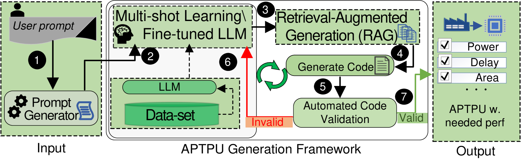
The image illustrates a technical workflow for an "APTPU Generation Framework." The diagram outlines an automated process that takes a user prompt as input, utilizes a combination of Multi-shot Learning, Fine-tuned LLMs, and Retrieval-Augmented Generation (RAG) to generate code, validates that code, and outputs an Application-Specific Tensor Processing Unit (APTPU) that meets specific performance constraints (Power, Delay, Area).
### Components/Axes
The diagram is divided into three distinct vertical regions:
**1. Input (Left Region)**
* **User Icon:** Represents the source of the input.
* **"User prompt":** The initial text input.
* **"Prompt Generator":** A processing block containing gear icons and a document icon.
* **Flow Arrow 1:** Directs the user prompt into the Prompt Generator.
**2. APTPU Generation Framework (Center Region)**
* **"Multi-shot Learning / Fine-tuned LLM":** A primary processing block (top-left).
* **"Retrieval-Augmented Generation (RAG)":** A secondary processing block (top-right) containing a document stack icon.
* **"LLM" & "Data-set":** A lower-left block containing a cylinder icon (Data-set) and a rounded rectangle (LLM).
* **"Generate Code":** A processing block (center-right) with a document icon.
* **"Automated Code Validation":** A processing block (bottom-right).
* **Flow Arrows:**
* **Arrow 2:** Connects the "Prompt Generator" to the "Multi-shot Learning / Fine-tuned LLM" block.
* **Arrow 3:** Connects "Multi-shot Learning / Fine-tuned LLM" to "Retrieval-Augmented Generation (RAG)".
* **Arrow 4:** Connects "RAG" to "Generate Code".
* **Arrow 5:** Connects "Generate Code" to "Automated Code Validation".
* **Arrow 6 (Red):** A feedback loop from "Automated Code Validation" (labeled "Invalid") back to "Multi-shot Learning / Fine-tuned LLM".
* **Arrow 7 (Green):** An output path from "Automated Code Validation" (labeled "Valid") to the Output region.
* **Circular Arrow:** Located between "Generate Code" and "Automated Code Validation," indicating an iterative loop.
**3. Output (Right Region)**
* **Icons:** A factory icon pointing to a chip icon.
* **Checklist:** Three items with checkboxes: "Power", "Delay", "Area".
* **"APTPU w. needed perf":** The final label for the output.
### Detailed Analysis
* **Workflow Logic:**
1. **Initialization:** The user provides a prompt, which is processed by the "Prompt Generator."
2. **Knowledge Integration:** The "Prompt Generator" output feeds into the "Multi-shot Learning / Fine-tuned LLM" block. Simultaneously, the "Data-set" informs the "LLM," which supports the "Multi-shot Learning" block.
3. **Contextual Generation:** The "Multi-shot Learning" block feeds into the "RAG" module, which retrieves relevant information to assist in code generation.
4. **Code Creation:** The "RAG" module triggers the "Generate Code" block.
5. **Validation Loop:** The generated code is sent to "Automated Code Validation."
* **If Invalid (Red Path):** The system loops back to the "Multi-shot Learning / Fine-tuned LLM" block (Arrow 6), likely to refine the model or the prompt based on the failure.
* **If Valid (Green Path):** The system proceeds to the Output (Arrow 7).
6. **Iterative Refinement:** The circular arrow between "Generate Code" and "Automated Code Validation" suggests that the system may attempt multiple code generation iterations before declaring a result "Valid" or "Invalid."
### Key Observations
* **Feedback Mechanism:** The presence of the red "Invalid" arrow (Arrow 6) indicates a closed-loop system where the validation results directly influence the learning/fine-tuning process.
* **Hardware Focus:** The output is explicitly tied to hardware metrics ("Power", "Delay", "Area"), implying this framework is designed for hardware synthesis or hardware description language (HDL) generation.
* **Modularity:** The framework separates the "Learning/Fine-tuning" phase from the "Generation/Validation" phase, allowing for specialized handling of data retrieval (RAG) versus code generation.
### Interpretation
This diagram describes an **Automated Hardware Design Flow**. The framework leverages Large Language Models (LLMs) to automate the creation of hardware designs (APTPUs).
The investigative reading suggests that the system is designed to solve the "hallucination" or "inaccuracy" problem common in LLM-generated code by implementing a strict validation gate. By feeding "Invalid" results back into the "Multi-shot Learning / Fine-tuned LLM" block, the system performs a form of **Reinforcement Learning from Code Validation (RLCV)**. It does not just generate code; it learns from its own failures to ensure the final output meets the physical constraints of Power, Delay, and Area, which are critical in semiconductor design. The framework essentially treats hardware design as a software generation problem that is constrained by physical reality.