\n
## Diagram: APTPU Generation Framework
### Overview
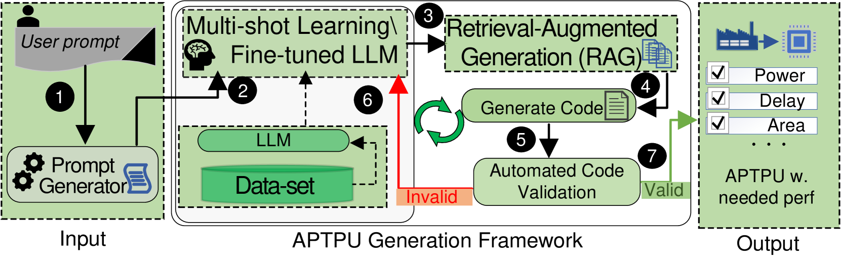
This diagram illustrates the workflow of an APTPU (likely Application-Specific Test Program Unit) Generation Framework. It depicts a process that takes a user prompt as input, utilizes multi-shot learning with a fine-tuned Large Language Model (LLM), employs Retrieval-Augmented Generation (RAG), validates generated code, and ultimately produces an APTPU with needed performance characteristics. The diagram uses numbered circles to indicate the flow of the process.
### Components/Axes
The diagram is divided into three main sections: "Input", "APTPU Generation Framework", and "Output".
Within the "APTPU Generation Framework" section, the following components are visible:
* **Multi-shot Learning & Fine-tuned LLM:** Contains an icon of a brain and the text "Fine-tuned LLM".
* **LLM:** A rectangular box labeled "LLM".
* **Data-set:** A rectangular box labeled "Data-set".
* **Retrieval-Augmented Generation (RAG):** A rectangular box labeled "Retrieval-Augmented Generation (RAG)".
* **Generate Code:** Text within the RAG box.
* **Automated Code Validation:** A rectangular box labeled "Automated Code Validation".
* **APTPU w. needed perf:** A rectangular box labeled "APTPU w. needed perf" with checkboxes next to "Power", "Delay", and "Area" and an ellipsis.
The diagram also includes the following labels:
* **User prompt:** Located at the top-left, indicating the input source.
* **Prompt Generator:** An icon of a gear and a book, indicating the component that generates prompts.
* **Invalid:** Labeling a dashed arrow returning from "Automated Code Validation" to "LLM".
* **Valid:** Labeling a solid arrow from "Automated Code Validation" to "APTPU w. needed perf".
Numbered circles indicate the process flow: 1 through 7.
### Detailed Analysis / Content Details
The process flow is as follows:
1. A "User prompt" enters the system.
2. The "User prompt" is processed by a "Prompt Generator".
3. The output of the "Prompt Generator" feeds into "Multi-shot Learning & Fine-tuned LLM".
4. The "Multi-shot Learning & Fine-tuned LLM" interacts with the "LLM" and "Data-set".
5. The "LLM" generates code, which is passed to "Retrieval-Augmented Generation (RAG)".
6. If the code generated by "RAG" is "Invalid", it is sent back to the "LLM" and "Data-set" for refinement. This is indicated by a dashed arrow.
7. If the code generated by "RAG" is "Valid", it is passed to "Automated Code Validation".
8. If the code is validated, it is used to generate an "APTPU w. needed perf". The output includes options for "Power", "Delay", and "Area".
### Key Observations
The diagram highlights a closed-loop system where code generation and validation are iterative. The use of "Multi-shot Learning" and "Retrieval-Augmented Generation" suggests a sophisticated approach to code generation, leveraging existing data and knowledge. The "Automated Code Validation" step is crucial for ensuring the quality and correctness of the generated APTPU. The checkboxes for "Power", "Delay", and "Area" indicate that these are key performance parameters being optimized.
### Interpretation
This diagram represents a modern approach to automated test program unit (APTPU) generation. It leverages the power of Large Language Models (LLMs) and machine learning techniques to streamline the process of creating specialized test programs. The iterative feedback loop between code generation and validation is essential for producing high-quality, reliable APTPUs. The inclusion of performance parameters like "Power", "Delay", and "Area" suggests that the framework is designed to optimize these critical aspects of the generated test programs. The diagram implies a shift from manual APTPU development to an automated, data-driven approach, potentially reducing development time and improving test coverage. The use of RAG suggests the LLM is not operating in isolation, but is augmented by a knowledge base to improve the quality of the generated code.