## Flowchart: APTPU Generation Framework
### Overview
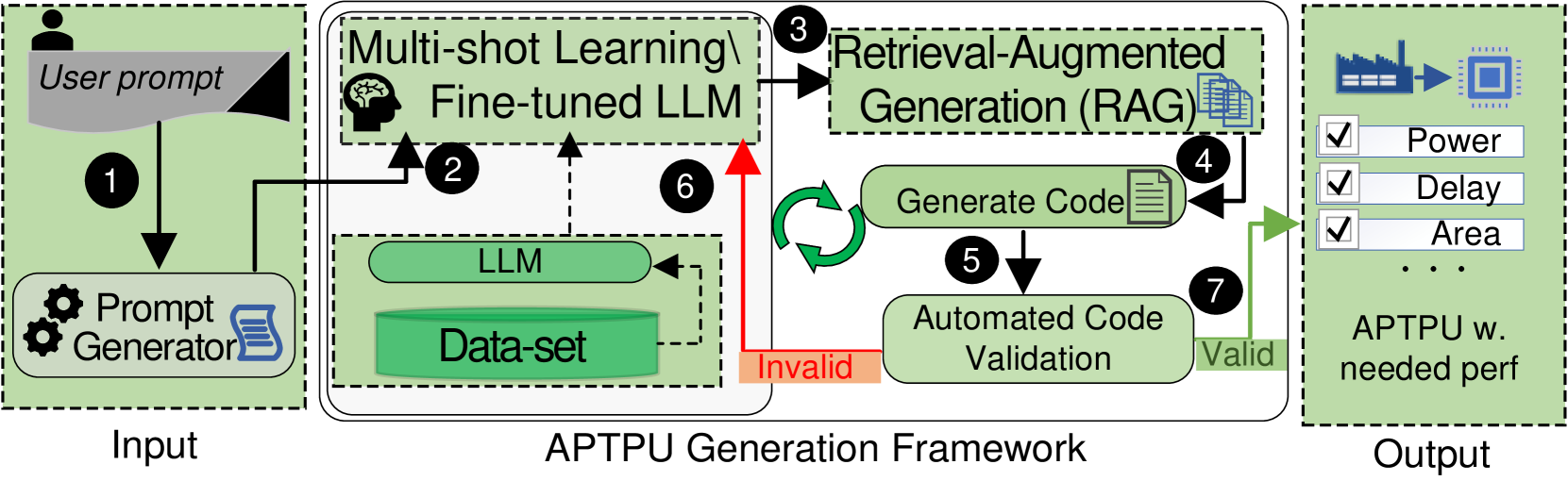
The diagram illustrates a multi-stage workflow for generating an APTPU (Application-Specific Technology Processing Unit) design. It begins with a user prompt, progresses through iterative code generation and validation, and concludes with an optimized APTPU output meeting performance criteria (Power, Delay, Area).
### Components/Axes
1. **Input Section**
- **User Prompt**: Initial input from a user (represented by a human icon).
- **Prompt Generator**: Converts the user prompt into structured input for the LLM.
2. **APTPU Generation Framework**
- **Multi-shot Learning / Fine-tuned LLM**: Processes the prompt using a large language model (LLM) trained on a dataset.
- **Retrieval-Augmented Generation (RAG)**: Generates code iteratively, with feedback loops for refinement.
- **Automated Code Validation**: Validates generated code (marked "Valid" or "Invalid").
- **Data-set**: A repository of training data for the LLM.
3. **Output Section**
- **APTPU w. needed perf**: Final output specifying an APTPU design optimized for Power, Delay, and Area.
### Detailed Analysis
- **Step 1**: User prompt → Prompt Generator → LLM input.
- **Step 2**: Multi-shot learning fine-tunes the LLM using the dataset.
- **Step 3**: RAG generates code (Step 4: "Generate Code").
- **Step 5**: Automated Code Validation checks validity.
- If **Invalid** (red arrow), the process loops back to RAG (Step 3).
- If **Valid** (green arrow), the workflow proceeds to output.
- **Step 6**: Data-set is referenced during LLM fine-tuning.
- **Step 7**: Final output includes APTPU specifications with performance metrics.
### Key Observations
- **Cyclical Refinement**: Code generation (Step 4) and validation (Step 5) form a feedback loop, ensuring iterative improvement.
- **Performance Optimization**: The output explicitly prioritizes Power, Delay, and Area, suggesting hardware-aware design constraints.
- **Validation Gatekeeper**: Invalid code is discarded, emphasizing quality control in the generation process.
### Interpretation
The framework demonstrates a closed-loop system where user intent is translated into optimized hardware design through iterative AI-driven code generation and validation. The integration of RAG and automated validation ensures robustness, while the focus on performance metrics aligns with hardware-software co-design principles. The absence of explicit numerical values suggests the diagram emphasizes process flow over quantitative results.