## Flowchart Diagram: Node-Based Process Flow
### Overview
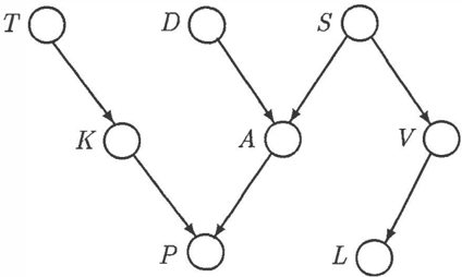
The image depicts a directed graph with eight nodes labeled T, K, P, A, D, S, V, and L. Arrows indicate directional relationships between nodes, forming a hierarchical and interconnected structure. No numerical data, scales, or legends are present.
### Components/Axes
- **Nodes**:
- T, K, P, A, D, S, V, L (all uppercase letters).
- **Edges**:
- Directed arrows connecting nodes (e.g., T → K, K → P, P → A, A → D, A → S, S → V, V → L).
- **Structure**:
- Central node **A** acts as a hub, connecting to **D**, **S**, and **P**.
- **P** connects to **K**, which connects to **T**.
- **S** connects to **V**, which connects to **L**.
- No cycles; all paths terminate at leaf nodes (T, D, L).
### Detailed Analysis
- **Node Connections**:
- T → K → P → A (left branch).
- A → D (direct connection).
- A → S → V → L (right branch).
- **Flow Direction**:
- All edges point downward or to the right, suggesting a top-down or left-to-right workflow.
- **Missing Elements**:
- No labels for edges, no numerical values, no color coding, and no explicit legend.
### Key Observations
- **Central Hub**: Node **A** is the most connected, serving as a convergence point for multiple paths.
- **Termination Points**: Nodes T, D, and L are endpoints with no outgoing edges.
- **Symmetry**: The left (T-K-P-A) and right (A-S-V-L) branches mirror each other in structure but differ in node labels.
### Interpretation
This diagram likely represents a process flow, decision tree, or organizational hierarchy. The central node **A** could symbolize a critical decision point or resource, with paths diverging to different outcomes (e.g., T, D, L). The absence of numerical data or labels suggests the focus is on relationships rather than quantitative metrics. The hierarchical design implies a structured workflow where each node represents a step or entity dependent on its predecessors.