## Diagram: System State Transitions and Global Fan-Out Process
### Overview
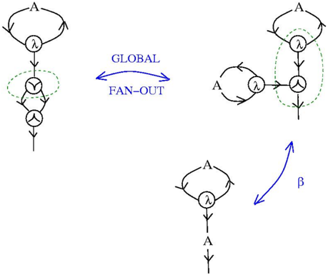
The diagram illustrates a multi-stage system with three primary components connected by labeled arrows. It depicts state transitions, global distribution mechanisms, and branching pathways. The system includes loops, conditional paths, and transformation processes.
### Components/Axes
1. **Left Structure**:
- Top loop labeled "A"
- Central node with "λ" (lambda)
- Two lower nodes:
- Left: "Y" (gamma)
- Right: "A"
- Dashed green oval encircling the lower nodes
- Vertical arrow exiting the bottom node
2. **Middle Structure**:
- Simple loop labeled "A"
- Central node with "λ"
- Direct connection to the right structure via "β" arrow
3. **Right Structure**:
- Top loop labeled "A"
- Central node with "λ"
- Lower node labeled "A" connected by dashed green line
- Dashed green oval encircling the entire structure
4. **Connecting Elements**:
- Blue bidirectional arrow between left and middle structures labeled "GLOBAL FAN-OUT"
- Blue arrow from middle to right structure labeled "β"
### Detailed Analysis
- **Left Structure**: Represents an initial state with a feedback loop ("A") and bifurcation into two paths ("Y" and "A"). The dashed oval suggests conditional processing of the lower nodes.
- **Middle Structure**: Simplified state with direct feedback loop, acting as an intermediary for global distribution.
- **Right Structure**: Final state with dual pathways - primary loop ("A") and optional secondary path ("A" via dashed line). The dashed oval indicates an alternative processing route.
- **Global Fan-Out**: Indicates bidirectional synchronization between initial and intermediary states.
- **β Transformation**: Represents a state transition or function application from intermediary to final state.
### Key Observations
1. The system exhibits hierarchical processing with three distinct stages
2. Dashed elements (oval boundaries and connecting lines) suggest optional/conditional operations
3. "Y" node introduces a unique pathway not present in other structures
4. "β" arrow implies irreversible transformation between states
5. All structures share identical "A" and "λ" labels, indicating conserved elements across states
### Interpretation
This diagram appears to model a computational or logical system with:
- **State Management**: The "λ" nodes likely represent state handlers or transformation functions
- **Control Flow**: The "A" loops suggest recurring processes or decision points
- **Global Coordination**: The "GLOBAL FAN-OUT" mechanism enables bidirectional communication between initial and intermediary states
- **Path Optimization**: The "β" transformation and dashed paths indicate potential optimization routes through the system
The presence of identical labels across structures suggests conserved elements in state transitions, while the unique "Y" node introduces system-specific processing. The bidirectional "GLOBAL FAN-OUT" implies a distributed architecture requiring synchronization between stages. The "β" transformation could represent a critical phase change or function application in the system's lifecycle.