## Diagram: Process Flow Comparison
### Overview
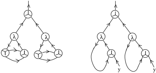
The image contains two side-by-side diagrams depicting hierarchical systems with nodes labeled "λ" (lambda) and "Y". Both diagrams show directional relationships via arrows, with the left diagram emphasizing bidirectional interactions and the right diagram incorporating feedback loops and unidirectional flows.
### Components/Axes
- **Nodes**:
- Top node: Labeled "λ" (lambda) in both diagrams.
- Intermediate nodes: Two "λ" nodes in each diagram, connected directly to the top λ.
- Bottom nodes: Three "Y" nodes in the left diagram; two "Y" nodes and a terminal "y" in the right diagram.
- **Arrows**:
- Left diagram: Bidirectional arrows between "Y" nodes (forming triangular loops).
- Right diagram: Unidirectional arrows from top λ to intermediate λ nodes, then to Y nodes. Feedback loops exist from Y nodes to the top λ, and a terminal "y" is labeled at the bottom.
### Detailed Analysis
- **Left Diagram**:
- The top λ branches into two intermediate λ nodes.
- Each intermediate λ connects to three Y nodes, which form closed triangular loops via bidirectional arrows.
- No terminal output is labeled.
- **Right Diagram**:
- The top λ branches into two intermediate λ nodes.
- Each intermediate λ connects to a single Y node.
- Y nodes have unidirectional arrows pointing back to the top λ (feedback loop).
- A terminal "y" is labeled at the bottom, suggesting an output or endpoint.
### Key Observations
1. **Bidirectional vs. Unidirectional Flow**:
- Left diagram emphasizes mutual interactions among Y nodes (bidirectional arrows).
- Right diagram introduces feedback loops (Y → top λ) and a terminal output ("y").
2. **Structural Symmetry**:
- Both diagrams share a hierarchical structure (top λ → intermediate λ → Y nodes).
- The right diagram simplifies the Y node connections (two Y nodes vs. three in the left).
3. **Terminal Output**:
- The right diagram explicitly labels a terminal "y", absent in the left diagram.
### Interpretation
- **System Behavior**:
- The left diagram likely represents a system with cyclical, interdependent processes (e.g., mutual feedback among components).
- The right diagram suggests a hierarchical system with feedback control (Y nodes regulating the top λ) and a defined output ("y").
- **Implications**:
- The bidirectional loops in the left diagram could model collaborative or competitive interactions (e.g., game theory scenarios).
- The right diagram’s feedback loop and terminal "y" might represent a regulated process with an endpoint, such as a control system or workflow.
- **Anomalies**:
- The absence of a terminal output in the left diagram implies an open or infinite system.
- The right diagram’s "y" label introduces ambiguity—it could denote a state, variable, or endpoint requiring further context.
## Notes
- No numerical data, axes, or legends are present.
- All labels are in English; no non-English text is observed.
- Arrows are unidirectional or bidirectional but lack explicit labels (e.g., "input," "output").
This analysis focuses on structural relationships and symbolic meaning, as the diagrams lack numerical or quantitative elements.