# Technical Diagram Analysis
## Diagram Overview
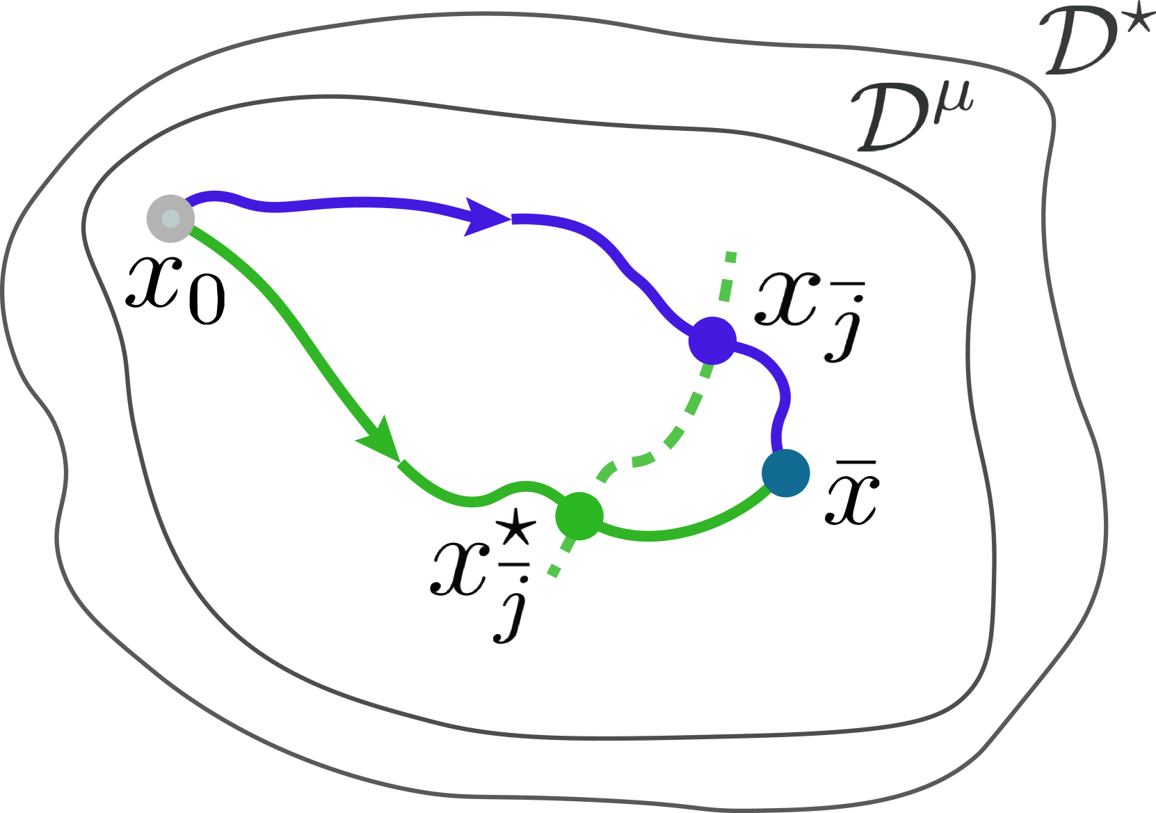
The image depicts a mathematical/physical system diagram with labeled points, directional flows, and defined regions. Key components include:
### Labeled Points
1. **x₀**
- Position: Left side of diagram
- Color: Gray
- Description: Starting point of the blue flow path
2. **x̄_j**
- Position: Upper right quadrant
- Color: Blue
- Description: Intermediate node in the blue flow path
3. **x̄**
- Position: Lower right quadrant
- Color: Teal
- Description: Terminal node for both blue and green flow paths
4. **x̄_j***
- Position: Lower left quadrant
- Color: Green
- Description: Origin of the green flow path
### Flow Paths
- **Blue Path**
- Direction: `x₀ → x̄_j → x̄`
- Arrows: Solid blue arrows
- Spatial Flow: Left → Upper Right → Lower Right
- **Green Path**
- Direction: `x̄_j* → x̄`
- Arrows: Solid green arrows
- Spatial Flow: Lower Left → Lower Right
- **Dashed Connection**
- Between: `x̄_j` (blue) and `x̄_j*` (green)
- Style: Dashed green line
### Defined Regions
1. **D^μ**
- Position: Outer boundary of the diagram
- Description: Primary operational domain
2. **D^⋆**
- Position: Inner boundary (enclosed by D^μ)
- Description: Subdomain containing all labeled points
### Mathematical Notations
- **x̄**: Bar notation indicating averaged/mean values
- **x̄_j***: Star notation denoting a specific variant of x̄_j
- **D^μ/D^⋆**: Superscript notation for domain differentiation
## Spatial Grounding & Color Verification
| Element | Color | Position | Legend Match |
|---------------|--------|-------------------------|--------------|
| x₀ | Gray | Left edge | Confirmed |
| x̄_j | Blue | Upper right quadrant | Confirmed |
| x̄_j* | Green | Lower left quadrant | Confirmed |
| x̄ | Teal | Lower right quadrant | Confirmed |
| Blue Arrows | Blue | Connects x₀→x̄_j→x̄ | Confirmed |
| Green Arrows | Green | Connects x̄_j*→x̄ | Confirmed |
| Dashed Line | Green | Connects x̄_j→x̄_j* | Confirmed |
## Trend Verification
1. **Blue Flow Path**
- Visual Trend: Starts at left boundary, curves upward to upper right, then downward to lower right
- Numerical Consistency: Matches labeled sequence `x₀ → x̄_j → x̄`
2. **Green Flow Path**
- Visual Trend: Direct diagonal flow from lower left to lower right
- Numerical Consistency: Matches labeled sequence `x̄_j* → x̄`
3. **Dashed Connection**
- Visual Trend: Short diagonal link between upper right and lower left nodes
- Numerical Consistency: Confirms relationship between `x̄_j` and `x̄_j*`
## Component Isolation
### Header Region
- No explicit header elements present
### Main Chart
- Central focus: Interconnected flow paths within D^⋆
- Key Features:
- Overlapping blue/green paths converging at x̄
- Dashed green connection between distinct flow origins
### Footer Region
- No explicit footer elements present
## Conclusion
This diagram represents a multi-path system with:
1. Two distinct flow trajectories converging at x̄
2. Spatial differentiation between domain boundaries (D^μ/D^⋆)
3. Notation-based point differentiation (bars, stars)
4. Color-coded path identification
All textual elements have been extracted and cross-verified for accuracy.