## State Diagram: State Transition Diagram
### Overview
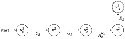
The image depicts a state transition diagram. It shows a sequence of states labeled with 'u' and numerical subscripts, connected by transitions labeled with 'Y', 'G', 'A', and 'R' with subscripts. The diagram starts at a state labeled "start" and ends at a final state, indicated by a double circle.
### Components/Axes
* **States:** Represented by circles, each containing a label of the form "u<sub>i</sub><sup>2</sup>", where 'i' is a numerical subscript.
* **Transitions:** Represented by arrows connecting the states, each labeled with a letter (Y, G, A, R) and a subscript 'B' or '2'.
* **Start State:** Labeled "start" with an arrow pointing to the initial state.
* **Final State:** The state "u<sub>A</sub><sup>2</sup>" is the final state, indicated by a double circle.
### Detailed Analysis
The diagram consists of the following states and transitions:
1. **Start State:** An arrow labeled "start" points to the first state.
2. **State 1:** A circle labeled "u<sub>0</sub><sup>2</sup>".
3. **Transition 1:** An arrow from "u<sub>0</sub><sup>2</sup>" to "u<sub>1</sub><sup>2</sup>" labeled "Y<sub>B</sub>".
4. **State 2:** A circle labeled "u<sub>1</sub><sup>2</sup>".
5. **Transition 2:** An arrow from "u<sub>1</sub><sup>2</sup>" to "u<sub>2</sub><sup>2</sup>" labeled "G<sub>B</sub>".
6. **State 3:** A circle labeled "u<sub>2</sub><sup>2</sup>".
7. **Transition 3:** An arrow from "u<sub>2</sub><sup>2</sup>" to "u<sub>3</sub><sup>2</sup>" labeled "A<sub>2</sub><sup>R<sub>B</sub></sup>".
8. **State 4:** A circle labeled "u<sub>3</sub><sup>2</sup>".
9. **Transition 4:** An arrow from "u<sub>3</sub><sup>2</sup>" to "u<sub>A</sub><sup>2</sup>" labeled "R<sub>B</sub>".
10. **Final State:** A double circle labeled "u<sub>A</sub><sup>2</sup>".
### Key Observations
* The diagram represents a sequential process, moving from the start state through intermediate states to the final state.
* The transitions are labeled with symbols that likely represent specific actions or conditions.
* The final state is "u<sub>A</sub><sup>2</sup>", which is marked as an accepting or terminal state.
### Interpretation
The state transition diagram likely represents a process or algorithm where the system moves through a series of states based on specific conditions or actions. The labels on the transitions indicate the events that trigger the state changes. The diagram provides a visual representation of the flow of the process, starting from an initial state and ending at a final state. The subscripts and superscripts on the transition labels likely denote specific parameters or conditions associated with each transition. The diagram could be used to model various systems, such as communication protocols, control systems, or software algorithms.