## State Transition Diagram: Sequential Process Flow
### Overview
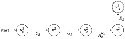
The image displays a linear state transition diagram, likely representing a sequential process, algorithm, or protocol. It consists of five circular nodes connected by directed edges (arrows) indicating a one-way flow from left to right, culminating in a final state. All text is in English with mathematical notation.
### Components/Axes
* **Nodes (States):** Five circles, each containing a state label.
* `u₀²` (leftmost)
* `u₁²`
* `u₂²`
* `u₃²`
* `uₐ²` (rightmost, double-circled)
* **Edges (Transitions):** Directed arrows connecting the nodes, each with a label.
* **Start Indicator:** The word "start" with an arrow pointing to the first node (`u₀²`).
* **Final State Indicator:** The node `uₐ²` is enclosed by a double circle, a standard notation for an accepting or final state in automata theory.
### Detailed Analysis
The diagram depicts a strict, linear sequence of states and transitions:
1. **Initial State:** The process begins at the state labeled `u₀²`, indicated by the "start" arrow.
2. **Transition 1:** From `u₀²`, a transition labeled `Y_B` leads to state `u₁²`.
3. **Transition 2:** From `u₁²`, a transition labeled `G_B` leads to state `u₂²`.
4. **Transition 3:** From `u₂²`, a transition labeled `A₂^{R_B}` leads to state `u₃²`. The label uses a superscript, indicating `A₂` with a superscript `R_B`.
5. **Final Transition:** From `u₃²`, a transition labeled `R_B` leads to the final state `uₐ²`.
**Spatial Layout:** The nodes are arranged in a horizontal line from left to right. The "start" label is positioned to the left of the first node. The final, double-circled node `uₐ²` is positioned at the far right, slightly elevated relative to the main line of nodes.
### Key Observations
* **Linear, Non-Branching Flow:** The process has a single, unambiguous path from start to finish with no loops or decision points.
* **Consistent Notation:** All state labels follow the pattern `u` with a subscript (0, 1, 2, 3, a) and a superscript `2`, except for the final state which has a subscript `a`.
* **Transition Label Pattern:** Transition labels (`Y_B`, `G_B`, `A₂^{R_B}`, `R_B`) appear to be symbolic, possibly representing actions, inputs, or conditions. The label `A₂^{R_B}` is the most complex, suggesting a compound operation or parameter.
* **Final State Distinction:** The double circle around `uₐ²` is the only visual element that breaks the pattern of single circles, clearly marking it as the termination point.
### Interpretation
This diagram models a deterministic, sequential system. Each state (`u₀²` through `u₃²`) represents a distinct stage, and each labeled transition represents a specific operation or event that must occur to advance to the next stage. The final state `uₐ²` represents the successful completion or acceptance condition of the process.
The notation suggests a technical context, potentially from fields like formal language theory, control systems, or computational models. The subscripts (0, 1, 2, 3, a) imply an ordered sequence, where 'a' likely stands for "accept" or "final." The superscript `2` on the states might denote a version, a phase, or a specific property common to all states in this sequence. The transition labels could be commands (`Y_B`, `G_B`), a specific action (`A₂`) parameterized by `R_B`, and a final release or reset signal (`R_B`). The diagram's purpose is to unambiguously define the only valid path through this specific process.