## Optical Setup Diagram
### Overview
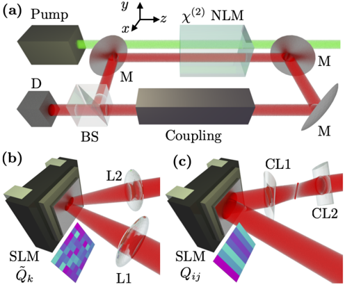
The image presents a schematic diagram of an optical setup, divided into three sub-figures labeled (a), (b), and (c). Sub-figure (a) depicts the main optical path involving a pump laser, a non-linear medium (NLM), mirrors, a beam splitter, and a detector. Sub-figures (b) and (c) show alternative configurations involving spatial light modulators (SLMs) and lenses.
### Components/Axes
**Sub-figure (a):**
* **Pump:** A rectangular block representing the pump laser source. A green beam emanates from it.
* **x, y, z axes:** A coordinate system is shown, with x and y in the plane of the image and z pointing out of the image.
* **χ^(2) NLM:** A rectangular block labeled "χ^(2) NLM" representing a second-order non-linear medium.
* **M:** Labeled mirrors.
* **BS:** A beam splitter.
* **D:** A detector.
* **Coupling:** A rectangular block labeled "Coupling".
**Sub-figure (b):**
* **SLM Q̃k:** A spatial light modulator labeled "SLM Q̃k" with a pixelated pattern displayed on it.
* **L1:** A lens.
* **L2:** Another lens.
**Sub-figure (c):**
* **SLM Qij:** A spatial light modulator labeled "SLM Qij" with a striped pattern displayed on it.
* **CL1:** A cylindrical lens.
* **CL2:** Another cylindrical lens.
### Detailed Analysis or ### Content Details
**Sub-figure (a):**
1. A green pump beam originates from the "Pump" and passes through a mirror "M" before entering the "χ^(2) NLM".
2. After passing through the NLM, the beam is directed by another mirror "M" towards the "Coupling" element.
3. The beam then encounters a beam splitter "BS".
4. One part of the beam is directed to the detector "D", while the other part continues along the optical path.
**Sub-figure (b):**
1. A red beam is incident on the "SLM Q̃k".
2. The modulated beam passes through lens "L1" and then lens "L2".
3. The SLM displays a pixelated pattern with varying shades of blue, green, and purple.
**Sub-figure (c):**
1. A red beam is incident on the "SLM Qij".
2. The modulated beam passes through cylindrical lens "CL1" and then cylindrical lens "CL2".
3. The SLM displays a striped pattern with alternating bands of blue, green, and purple.
### Key Observations
* Sub-figure (a) shows a typical optical setup for second-harmonic generation or similar non-linear processes.
* Sub-figures (b) and (c) demonstrate the use of spatial light modulators to shape the beam profile.
* The patterns displayed on the SLMs in (b) and (c) are different, suggesting different modulation schemes.
* The use of cylindrical lenses in (c) suggests the shaping of the beam in one dimension.
### Interpretation
The diagram illustrates different configurations of an optical system. Sub-figure (a) shows a fundamental setup for non-linear optics, while sub-figures (b) and (c) demonstrate advanced beam shaping techniques using spatial light modulators and lenses. The SLMs allow for dynamic control of the beam profile, which can be used for various applications such as optical trapping, microscopy, and optical communication. The use of different lens types (spherical vs. cylindrical) indicates different beam shaping strategies. The overall setup suggests a flexible platform for exploring and manipulating light.